

Section 5.3: Propagation Modes and Paths #
Now that you understand the ionosphere’s structure and the solar forces that control it, let’s see how your signals actually navigate this dynamic system. Your signal leaves the antenna and heads skyward. Sometimes it bounces once and lands 2,000 miles away. Sometimes it scatters into unexpected places or takes paths that seem to defy logic. Understanding these propagation modes and paths helps you predict which bands will work and when contacts become possible.
Skip Propagation: How Signals Circle the Globe #
HF signals use the ionosphere as a natural relay station, bouncing between Earth and sky to reach distant locations. Your signal travels upward, refracts off an ionospheric layer, returns to Earth, reflects from the surface, and heads skyward again. Each bounce extends your reach by hundreds or thousands of miles.
The distance each hop covers depends on which ionospheric layer does the refracting.
Key Information: Maximum single-hop distance:
- F2 region: approximately 2,500 miles
- E region: approximately 1,200 miles
A single F2 hop can cross a narrow part of the Atlantic. Under suitable conditions, three hops can cover up to roughly 7,500 miles; real hop lengths vary. The higher layer provides longer hops because geometry favors distance—like throwing a ball against a higher ceiling lets it travel farther before landing.
Short Path vs. Long Path #
Every distant station offers two possible paths around our spherical Earth. Short path takes the direct route—the shortest distance between two points on the globe. From New York to Tokyo, the short great-circle route heads roughly north-northwest and covers about 6,700 miles.
Long path heads the opposite direction, the long way around the world. That same New York-to-Tokyo contact would point south-southeast, traveling about 18,100 miles along the other arc of that great circle. This longer journey sometimes encounters better propagation conditions than the direct route.
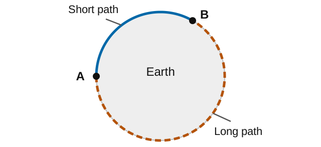
When both paths open simultaneously, you may hear a useful clue.
Key Information: A characteristic of skywave signals arriving by both short-path and long-path propagation is a slightly delayed echo.
In our example, the surface routes differ by about 11,400 miles—roughly 60 milliseconds of travel time at the speed of light. The actual ionospheric paths are somewhat longer. The later arrival can create a distinctive hollow sound. It is a clue to check the opposite beam heading, though other multiple paths can also cause echoes.
Scatter Propagation: Signals from the Impossible Zone #
The skip zone should be silent—too far for ground wave, too close for normal skip. Yet sometimes weak signals appear from this “dead” zone through scatter propagation. Instead of clean refraction, your signal hits ionospheric irregularities and scatters in multiple directions like light hitting a disco ball.
Key Information: HF scatter propagation characteristics:
- Creates signals with a fluttering sound
- Sounds distorted due to energy scattered through multiple paths
- Allows signals to be heard in the transmitting station’s skip zone
- Signals are usually weak because only a small part of the energy scatters into the skip zone
The multiple scattered signals arrive with slightly different timing and phase, combining at your receiver to produce the unmistakable warbling sound of scatter propagation. Most of your signal continues on its normal path or gets absorbed—only a tiny fraction scatters back toward the skip zone, explaining why these signals barely rise above the noise floor. Digital modes excel here since they can decode signals too weak for voice communication.
NVIS: Reliable Regional Coverage #
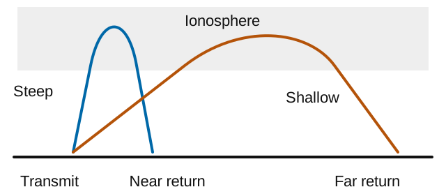
Sometimes you need coverage across a region a few hundred miles wide, including places inside the usual skip zone. Near Vertical Incidence Skywave propagation fills this need by launching signals nearly straight up.
Key Information: NVIS propagation is short distance MF or HF propagation using high radiation angles.
Instead of using low angles for distance, NVIS uses high angles for area coverage. The ionosphere acts like an umbrella, reflecting your nearly vertical signal back down in a circular pattern around your station. With suitable frequencies and ionospheric conditions, this can fill in the usual skip zone and reach stations out to a few hundred miles away.
NVIS requires the right antenna setup and frequency. Low horizontal antennas (0.1 to 0.25 wavelengths high) produce the high-angle radiation needed. As we saw in the previous chapter, this height favors a high-angle pattern; the details depend on height and ground conditions. Frequency must be below the critical frequency for vertical reflection but high enough to avoid excessive D-region absorption. During daylight, 40 or 60 meters may be useful choices. After dark, 80 or 160 meters may work better as ionization falls. Check the current path: none of these bands is always suitable.
Emergency services rely on NVIS because it provides dependable regional coverage when infrastructure fails. The mode excels for disaster communications, nets covering mountainous terrain, and any application requiring solid coverage within a few hundred miles.
Understanding MUF and Path Selection #
Choosing among these paths also means choosing a frequency. Earlier in this chapter, we introduced MUF (Maximum Usable Frequency) for a particular path; now let’s compare how it can differ between paths.
Key Information:
- MUF is affected by path distance and location, time of day and season, and solar radiation and ionospheric disturbances.
- For long-distance skip propagation, the least attenuation occurs at frequencies just below the MUF.
Every path between two stations has its own MUF at any given moment. The path from New York to London might support 21 MHz while New York to Tokyo peaks at 14 MHz. These variations depend on ionospheric conditions along the entire path, not just at the endpoints.
Choosing the right frequency relative to the MUF determines propagation success. Operating just below the MUF reduces absorption while the ionosphere can still return the signal. That explains the exam’s least-attenuation answer. The MUF changes, though: a little more room below it may keep a link working when conditions shift. Least attenuation does not necessarily mean minimum fading or greatest reliability.
Monitoring Real Propagation #
Modern technology gives you another way to check band conditions.
Key Information: Current propagation can be determined by using a network of automated receiving stations on the internet to see where your transmissions are being received.
Networks like the Reverse Beacon Network and PSK Reporter show where participating receivers have heard signals. Send a CQ in a mode the network monitors, and reports may appear within seconds on the Reverse Beacon Network or within a few minutes on PSK Reporter. That is direct evidence of a working path. No report does not prove the path is closed: a receiver may be absent, busy or unable to decode your signal.
Seasonal Propagation Patterns #
Finding an open path is only part of the job; your signal also has to compete with noise. Summer brings particular challenges to HF operation.
Key Information: Lower HF frequencies typically experience high levels of atmospheric noise or static during summer.
Thunderstorms across the tropics and temperate regions generate radio noise that plagues 160, 80, and 40 meters from late spring through early fall. Each lightning strike acts as a broadband transmitter, raising noise levels that can bury weak signals. The lower the frequency, the worse the noise. Operators often call this static QRN and interference from other signals QRM; the distinction is noise versus interfering signals, not simply natural versus man-made. Filters and noise controls can help, but they cannot always separate noise from a wanted signal in the same passband.
Winter often brings less local thunderstorm noise, though you can still hear distant storms. The longer darkness hours favor low-band propagation. Spring and fall can also offer useful DX openings; seasonal ionospheric changes and the daylight along each path matter.
From Propagation Science to Practical Operation #
Band choice and timing are only part of getting on the air. The next part turns to the station you operate, starting with safety before moving into equipment setup and operating procedures.


 2,500 miles