



Section 4.5: Mobile and Portable Antennas #
Freedom to roam with radio—that’s the promise of mobile and portable operation. The General privileges you’re studying for can turn a road trip into a chance to make worldwide contacts, every park visit into a Parks On The Air (POTA) event, and every emergency into a chance to provide vital communications. The challenge? Creating effective antennas that can travel with you while still getting your signal out to the world.
Engineering Magic: Making Big Antennas Small #
Picture trying to mount a 33-foot whip antenna on your car for 40-meter operation—it would add some definite challenges to the trip! Yet thousands of hams work HF mobile every day, making contacts around the world with antennas significantly shorter than that. The secret lies in clever engineering that makes the best use of the antenna you have by making it “appear” the correct length electrically.
Remember those resonant circuits from Chapter 1? We use the same principle here—adding inductance or capacitance to cancel out the antenna’s reactance at our desired frequency. Below its first resonance, a physically short whip has capacitive reactance, so we add inductance to bring it to resonance where the impedance becomes purely resistive.
The two main approaches are capacitance hats and loading coils. These devices add electrical length without adding physical height, letting you fit effective HF antennas on vehicles.
Key Information: A capacitance hat on a mobile antenna is used to electrically lengthen a physically short antenna.
Think of a capacitance hat as spreading out the antenna’s electrical field at the top, where current is lowest. Those horizontal spokes or discs you see on mobile antennas are typically 4-8 radial wires or a solid metal disk mounted at the antenna tip. They create capacitance to ground, reducing the capacitive reactance of the short antenna. Loading coils work more directly—they add inductive reactance that cancels the antenna’s capacitive reactance, bringing the total reactance to zero at resonance.
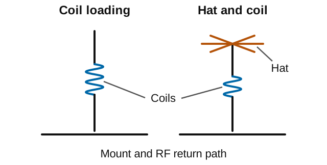
Every engineering solution has trade-offs. When you shorten an antenna and add components to resonate it, you’re creating a high-Q circuit with a narrow bandwidth.
Q describes stored energy compared with the energy radiated or lost each cycle. A high-Q resonant system tends to change its match quickly as frequency changes.
Key Information: One disadvantage of using a shortened mobile antenna as opposed to a full-size antenna is operating bandwidth may be very limited.
This narrow bandwidth means you might need to retune when moving just a few kilohertz up or down the band. Many mobile operators solve this with automatic antenna tuners or motorized antennas that adjust on the fly.
A tuner at the radio changes the load seen by the radio; it cannot remove losses in the short antenna. A motorized loading adjustment changes the antenna itself.
Taming Tip Discharge: Corona Protection #
That innocent-looking ball at the tip of mobile HF antennas serves a critical purpose. When you key up with 100 watts into a shortened antenna, the high Q of the resonant circuit creates extreme voltage multiplication—potentially thousands of volts at the antenna tip!
Key Information: The purpose of a corona ball on an HF mobile antenna is to reduce RF voltage discharge from the tip of the antenna while transmitting.
Corona discharge happens when high voltage ionizes the air, creating a bluish glow and crackling sound around your antenna tip. Besides wasting power, this creates broadband noise that interferes with nearby electronics. The corona ball spreads out the electric field, reducing field concentration and the chance of discharge. The rounded tip helps; it does not guarantee no sparking and does not protect against lightning.
The Mobile Reality Check: Efficiency and Power #
Here’s the truth about mobile HF: more transmitter power doesn’t fix an inefficient antenna system. The laws of physics are unforgiving when it comes to shortened antennas.
Key Information: The efficiency of the electrically short antenna is what most limits an HF mobile installation.
A full-size quarter-wave vertical might radiate 90% of your power. Shrink it to fit on a car, and efficiency can fall to 10% or less—meaning 90 watts or more of a 100-watt signal becomes heat in the coil, conductors and return path instead of radiating! A short antenna may have only a few ohms of radiation resistance. If the coil and return path add more resistance than that, more power becomes heat than radio waves.
To get the best efficiency, mount antennas as high as possible on the vehicle, use the largest diameter conductor that’s practical, ensure excellent ground connections to the vehicle body, and keep losses in the loading system minimal.
The Screwdriver Revolution: Tuning on the Fly #
Imagine changing bands while cruising down the highway, never stopping to adjust your antenna. That’s the promise of the “screwdriver” antenna—one of amateur radio’s most ingenious mobile solutions. Many models cover a wide range of HF bands with the push of a button; check the particular antenna and whip’s range, and make adjustments without distracting the driver.
The name refers to the motorized loading adjustment.
Key Information: A “screwdriver” mobile antenna adjusts its feed point impedance by varying the base loading inductance.
Inside that cylindrical base sits a motor-driven variable inductor. As the motor turns, it changes the inductance to cancel the antenna’s capacitive reactance at your desired frequency—just like adjusting a variable capacitor in a tuned circuit. Modern versions include controllers that remember settings for each band, letting you change bands as easily as changing channels on your car radio.
Multiband Magic: Trap Antennas #
Whether mobile or portable, carrying separate antennas for each band quickly becomes impractical. Enter the trap antenna—a clever solution that packs multiple resonant antennas into one physical structure.
Key Information: The primary function of antenna traps is to enable multiband operation.
Traps are parallel LC circuits that act as frequency-selective switches. At their resonant frequency, these circuits present high impedance (remember from Chapter 1?), effectively “cutting off” the antenna at that point. Below trap resonance, they act inductively: more of the antenna participates, and the trap’s loading helps establish a lower-frequency resonance. This lets one antenna work like multiple antennas of different lengths—a 40/20/15 meter trap vertical automatically selects the right electrical length for each band.
The multiband convenience comes with a catch. These antennas can radiate on frequencies you didn’t intend.
Key Information: A disadvantage of multiband antennas is that they have poor harmonic rejection.
When your antenna resonates on multiple amateur bands, it might also resonate on harmonics of your operating frequency. Transmit on 7 MHz, and your second harmonic at 14 MHz might radiate efficiently too—potentially causing interference.
The transmitter creates that unwanted harmonic; the antenna may radiate it efficiently rather than rejecting it. Since the antenna can’t distinguish between your desired signal and its harmonics, good transmitter filtering becomes essential with multiband antennas.
A Mobile VHF Option #
The Halo solves the VHF mobile SSB problem—you need horizontal polarization but can’t rotate an antenna while driving.
Key Information: The maximum radiation from a VHF/UHF “halo” antenna is omnidirectional in the plane of the halo.
It’s roughly a half-wave element bent into a loop shape, with its ends close but not joined; that gap is not generally the feed point. Mounted horizontally, you get horizontal polarization for SSB work with roughly 360-degree coverage—perfect for VHF contest operators who travel between locations and need to work stations in any direction without stopping.
From Antennas to Propagation #
With shortened antennas, the same physics applies whether you are using a screwdriver on a vehicle or a loaded vertical in the field—adding reactance to achieve resonance despite size limitations.
Portable operation need not mean a shortened antenna. If there’s room for a full-size wire dipole, you can use the same design as at home and avoid losses added just to make it smaller.
Your antennas launch signals into space, but that’s only half the story. In the next chapter, we’ll discover how the ionosphere bends those signals around the Earth and why bands open and close. Understanding propagation transforms random band-scanning into strategic operating.



 To electrically lengthen a physically short antenna