



Section 4.4: Directional Antennas #
Picture this: you’re trying to work a rare DX station in Japan from your station in California. The pile-up is fierce—hundreds of stations all calling at once. Then you turn your beam toward Japan, and the scratchy signal becomes clear. You call again, and the operator comes right back with your call sign. You’re still running 100 watts, but your antenna now puts more of your signal toward Japan and picks up the reply more strongly, too. That’s the magic of directional antennas, and with General privileges reaching all nine HF amateur bands, they can be a powerful tool for making those dream contacts.
The Yagi Antenna: Your Signal Spotlight #
The Yagi antenna transforms your station from a campfire to a searchlight. In the previous section, we saw how a dipole radiates most strongly broadside to its wire. A Yagi concentrates that energy further into a beam. This concentration of power is what lets modest stations work the world.
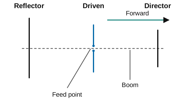
A Yagi has aluminum elements mounted on a horizontal support called a boom. It uses three types of elements working together:
Key Information:
- The approximate length of the driven element of a Yagi antenna is 1/2 wavelength.
- In a three-element Yagi, the reflector is longer and the director is shorter than the driven element.
The Driven Element is the heart of the antenna—the only element connected to your coax. This roughly half-wavelength element resonates near your operating frequency in many designs, just like a dipole. We add parasitic elements (not driven directly by the feed line) that interact with the driven element’s radiated field.
The Reflector sits behind the driven element, slightly longer than the driven element. When RF from the driven element reaches it, the reflector re-radiates that energy back toward the front of the antenna, reinforcing the forward signal.
Directors sit in front of the driven element, slightly shorter than the driven element. They “pull” the signal forward, further concentrating energy in the desired direction.
This relationship between element lengths helps create the directional pattern. The elements work through induced currents. Their fields add in the forward direction and partly cancel elsewhere; lengths and spacing set the relative phases.
Matching the Yagi #
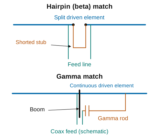
The driven element also needs a good match to the feed line. Two common matching systems use rods or short pieces of transmission line at its feed point.
Beta Match (Hairpin Match) #
Key Information: A beta or hairpin match is a shorted transmission line stub placed at the feed point of a Yagi antenna to provide impedance matching.
The beta match uses a shorted section of transmission line (the “hairpin”) placed in parallel with the feed point of an antenna element. With a suitably shortened driven element, the hairpin’s inductive reactance works with the element’s capacitive reactance to transform the feed-point impedance.
This matching system is popular for Yagi antennas because:
- It’s relatively simple to construct
- You can adjust it by changing the length or shape of the hairpin
- It provides a good match across a reasonable bandwidth
Gamma Match #
The gamma match is another common approach for directive antennas:
Key Information: A gamma match with a Yagi antenna does not require the driven element to be insulated from the boom.
The gamma match offers several advantages:
- Allows direct connection of the boom to the driven element without insulation
- Provides adjustable impedance matching; a separate common-mode choke may still be useful
- Lets you adjust the match by changing the gamma rod length and capacitor setting
Building Better Beams: Performance Factors #
When you’re ready to put up a beam antenna, understanding what makes one Yagi perform better than another helps you choose wisely. Every design decision involves tradeoffs between gain, bandwidth, and physical size.
Adding More Elements is the most obvious way to improve a Yagi. Each additional director further focuses your signal, squeezing more gain from the same input power.
Key Information: Increasing boom length and adding directors to a Yagi antenna primarily increases its gain.
Adding directors with the right lengths and spacing can narrow the beam further. For example, if one design has 3 dB more gain than another using the same reference, that doubles its effective power in the comparison direction! Check whether the gain is stated in dBi or dBd, as Section 1.5 explains.
Element Diameter affects how your antenna performs across a band. HF bands are wide—20 meters spans 350 kHz—and you want good SWR across the entire range.
Key Information: Using larger-diameter elements would increase the bandwidth of a Yagi antenna.
Thicker elements are like wider pipes—they’re more forgiving of slight frequency changes. This is why commercial Yagis often use aluminum tubing rather than wire elements. Here, “more forgiving” means the feed-point impedance tends to change less rapidly with frequency, so SWR stays within a useful limit over a wider range.
Understanding Antenna Specifications #
The Main Lobe is where your antenna concentrates its power—the primary direction of radiation.
Key Information: The main lobe of a directive antenna is the direction of maximum radiated field strength from the antenna.
The width of this main lobe, called its beamwidth, determines how precisely you need to aim. A sharp, narrow beam requires accurate pointing but delivers maximum punch to your target. A broader beam is more forgiving but spreads your power over a wider area.
Front-to-Back Ratio tells you how well your antenna ignores signals from behind.
Key Information: Front-to-back ratio means the power radiated in the major lobe compared to that in the opposite direction.
Imagine working Europe from the East Coast while a loud station in California is on the same frequency. A Yagi with a 20 dB front-to-back ratio gives equal-strength arriving signals a 100-to-1 received-power difference between front and back. The actual California and European signals also depend on their powers and paths. It’s like having selective hearing that focuses on the conversation you want!
Optimizing Your Beam #
Every Yagi design involves compromises. Want maximum gain? You might sacrifice bandwidth. Need to cover an entire band with low SWR? You might give up some gain. The beauty is that you can tailor the antenna to your operating style.
Key Information: Forward gain, front-to-back ratio, and SWR bandwidth of a Yagi antenna can all be optimized by adjusting the physical length of the boom, the number of elements on the boom, and the spacing of each element along the boom.
Computer modeling has revolutionized antenna design. Modern Yagis are optimized for specific goals—DX chasers might choose maximum forward gain, contesters often prefer wide bandwidth for quick frequency changes, and those fighting noise might optimize for front-to-back ratio.
Stacking: When One Antenna Isn’t Enough #
Here’s an interesting trick when you want more gain from your antenna system: You can combine multiple antennas together using a method called “stacking.” The principle is to combine the antennas’ patterns using suitable spacing and relative phase; the total transmitter power is shared between them.
The catch? Spacing and feed phase must suit the design; the exam’s free-space example uses in-phase antennas half a wavelength apart. Get it right and you gain 3 dB—like doubling your transmitter power. Get it wrong and signals can partly cancel, reducing gain or sending the beam in the wrong direction.
Key Information:
- In free space, the gain of two 3-element, horizontally polarized Yagi antennas spaced vertically 1/2 wavelength apart is approximately 3 dB higher than a single 3-element Yagi.
- An advantage of vertically stacking horizontally polarized Yagi antennas is that it narrows the main lobe in elevation.
That 3 dB improvement means your 100-watt signal now hits like 200 watts, and it helps on receive too. But the benefits go beyond raw gain. Think of narrowing a floodlight’s beam, this time in elevation—the angle above the horizon. More energy is concentrated in a smaller vertical range, rather than narrowing the beam in azimuth—around the horizon.
That does not guarantee a lower takeoff angle (the elevation of the main lobe): antenna height, spacing, feed phase and ground reflections all affect where the main lobe points. High-angle radiation can also be useful for regional contacts, as we saw with NVIS in the previous section.
While stacked Yagis offer ultimate performance on a single band, many General operators need a more versatile solution for their multi-band privileges.
The Log Periodic: One Antenna, Many Bands #
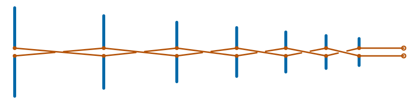
General privileges include all nine HF amateur bands. Wouldn’t it be nice to cover several of them with one beam? A log periodic dipole array (LPDA) is a directional antenna made from a row of dipoles of progressively different lengths. All connect to a common feed system.
Key Information:
- An advantage of a log periodic antenna is wide bandwidth.
- A log periodic antenna has element length and spacing vary logarithmically along the boom.
Where a monoband Yagi is optimized for one band, a log periodic covers a huge frequency range—often 14 to 30 MHz in a single antenna. The secret lies in its unique construction. Picture a Yagi where each element is scaled down from the one before it by a constant ratio. The longest elements resonate on the lowest frequency, while progressively shorter elements handle higher frequencies. As you change bands, different groups of elements “wake up” and become active.
Unlike the Yagi’s parasitic elements, LPDA elements connect to a feed structure. Check the model’s frequency range; a 14–30 MHz design does not cover all nine HF bands.
The tradeoff? An LPDA may provide less gain than a monoband Yagi of comparable size; the difference depends on the designs. But for many operators, the convenience of instant band changes without retuning or switching antennas is worth the modest gain sacrifice.
Specialized Antennas for Specific Needs #
Beyond Yagis and log periodics, two specialized directional receiving antennas solve unique challenges worth knowing about.
Small Loops (less than 1/10 wavelength circumference) excel at one thing: deep nulls for direction finding or interference rejection.
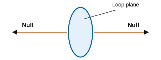
Key Information: An electrically small loop (less than 1/10 wavelength in circumference) has nulls in its radiation pattern broadside to the loop.
Rotate the loop until a signal disappears, and you know the source is perpendicular to the loop plane. There are two opposite null directions, so that alone does not tell you which side contains the source.
That neighbor’s plasma TV wreaking havoc on 40 meters? Orient a small receiving loop to null it out.
The Beverage is the ultimate low-band DX receiving antenna—a simple long wire (500-1000 feet) mounted low with a terminating resistor.
Key Information: The primary use of a Beverage antenna is directional receiving for MF and low HF bands.
Terrible efficiency for transmitting, but outstanding for pulling weak 160 and 80-meter DX from the noise because its directivity can improve the wanted signal compared with noise from other directions. Top DXpeditions often deploy multiple Beverages in different directions for optimal reception.
Making Directional Antennas Work for You #
Before you start shopping for that dream beam antenna, let’s talk about the realities of putting one up.
Physical Size becomes a real consideration on HF. A full-size three-element Yagi for 20 meters can be over 35 feet wide, with a boom tens of feet long. Scale a similar design to 40 meters and those dimensions roughly double! Many hams start with a beam for 15 or 10 meters where the antennas are manageable, then work up to larger antennas as they gain experience.
Mechanical Requirements go beyond just the antenna. A beam needs:
- A tower or mast strong enough to support the weight
- A rotator to point it where you want
- Proper guying to handle wind loads
- Safe installation practices—working at height is dangerous, and power lines are deadly
Many hams wisely hire professionals for tower work. There’s no shame in prioritizing safety over savings.
The Neighbor Factor is real. Some antenna installations have legal protections, but local rules and private restrictions still matter (see Section 9.2). Maintaining good relationships matters too. Many hams find that explaining amateur radio’s public service role helps gain acceptance. Others choose less visually imposing options like hex beams or compact tribanders.
Budget Reality hits hard when you price a complete beam station. A modest tribander, 50-foot tower, rotator, and installation can easily exceed $5,000. But don’t despair—many successful DXers started with wire antennas and upgraded gradually. Some build their own Yagis from hardware store materials, learning valuable lessons along the way.
Your Path to Directional Success #
Some hams find creative solutions—starting small with VHF/UHF Yagis, trying portable operations with lightweight beams, building fixed direction arrays without rotators, or sharing resources through club stations.
Taking the radio on the road adds another challenge: fitting an effective HF antenna on a vehicle or carrying one to a temporary site. In the next section, we’ll look at the designs and tradeoffs that make mobile and portable antennas practical.



 1/2 wavelength