



Section 4.3: Dipoles and Vertical Antennas #
A good match gets power into the antenna, but you still need a design that fits your station. Good news—simple wire dipoles and vertical antennas make successful HF contacts every day. Their height, shape, and feed-point position can help you make the most of the space you have.
Dipole Antennas: Your Gateway to HF Success #
Picture this: with just two pieces of wire and some coax, you can work stations on the other side of the world. A basic half-wave dipole has two wire arms, each about a quarter wavelength long, with the feed line connected at the center. Its radiation pattern helps you decide how to position those wires.
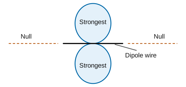
The drawing shows the dipole in free space: an ideal setting without the ground or nearby objects affecting it. The two lobes show where its signal is strongest.
Key Information: The radiation pattern of a dipole antenna in free space, in a plane containing the conductor, is a figure-eight at right angles to the antenna.
This figure-eight pattern means your signal radiates strongest broadside to the wire—perpendicular to its length—with nulls off the ends. The drawing is a flat slice through the wire and its three-dimensional pattern. Orient your dipole so its broadside faces the areas you want to reach, whether that’s Europe, Japan, or your favorite net control station.
Height Transforms Your Dipole’s Performance #
A dipole’s height affects both its radiation pattern and its feed-point impedance. Moving the same wire can change which stations you reach and the SWR your radio sees.
When you mount a dipole low (less than a half wavelength high), reflections from the ground reshape its radiation pattern. At high elevation angles—angles above the horizon—the signal spreads almost evenly in every compass direction, or azimuth.
Key Information:
- If a horizontal dipole HF antenna is less than 1/2 wavelength high, its azimuthal radiation pattern is almost omnidirectional at elevation angles higher than about 45 degrees
- The feed point impedance of a horizontal 1/2 wave dipole antenna steadily decreases as its height is reduced to 1/10 wavelength above ground
Near the ground, lowering the wire tends to lower its feed-point impedance. At greater heights, ground reflections can make the impedance rise or fall. Check the SWR after the antenna is at its working height.
A low dipole sends much of its signal upward. This suits NVIS (Near Vertical Incidence Skywave), which uses high-angle signals for regional contacts. A higher dipole can provide more useful low-angle radiation for DX. We’ll return to NVIS later in this section.
Feed Point Magic: Controlling Impedance #
Height isn’t the only thing that affects the match. Where you connect the feed line matters too. A dipole presents different impedances at different points along its length.
Key Information: The feed point impedance of a 1/2 wave dipole steadily increases as the feed point is moved from the center toward the ends.
At the center, current is high and voltage is lower, giving a relatively low feed-point impedance. Toward the ends, current falls and voltage rises, so impedance increases into the thousands of ohms. That’s why a center-fed dipole can work well with 50-ohm coax, while feeding the same antenna at one end calls for a matching transformer.
A center-fed half-wave dipole in free space has a feed-point resistance of roughly 73 ohms. Height and surroundings affect the value you measure on an installed antenna.
Building Your Dipole: From Formula to Reality #
Once you’ve chosen a location, you need to cut the wire to length. A practical half-wave dipole is slightly shorter than a half wavelength in free space. The familiar factor of 468 accounts for that shortening and gives a useful starting length, using frequency in MHz:
Let’s see this formula in action for two popular HF bands.
Key Information:
- The approximate length for a 1/2 wave dipole antenna cut for 14.250 MHz is 33 feet
- The approximate length for a 1/2 wave dipole antenna cut for 3.550 MHz is 132 feet
For 14.250 MHz, feet; for 3.550 MHz, feet. These are total tip-to-tip lengths. Each arm is half that: about 16.4 feet or 66 feet.
Cut a little long, then measure and adjust with the antenna in its intended position. That 33-foot dipole for 20 meters fits in many suburban yards, while the 132-foot 80-meter dipole might require some creative installation techniques!
The Inverted V: One High Support #
Not everyone has two tall supports perfectly spaced for a flat dipole. An inverted V raises the center on one high support and lets the two wire legs slope down to lower supports at the ends.
Key Information: The common name of a dipole with a single central support is an inverted V.
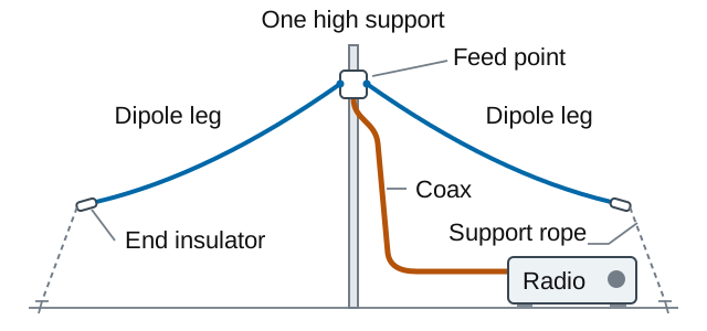
Besides saving a tall support, the sloping legs change the radiation pattern and feed-point impedance. They can give useful coverage in more directions than a flat dipole. The impedance may also be near 50 ohms, though the angle, height, and surroundings affect the match. Measure the SWR once it’s up. For many yards, an inverted V is a good way to fit a useful dipole into the available space.
End-Fed Antennas: Feed Line Freedom #
Sometimes your preferred antenna location puts the center right where you can’t reach it—over a pond or high in a tree. An end-fed half-wave (EFHW) antenna moves the feed point to one end, giving you more freedom to put the connection somewhere accessible.
That convenience comes with a matching challenge. Remember how moving the feed point toward the ends increases impedance? At the end of a half-wave antenna, it reaches several thousand ohms.
Key Information: The feed point impedance of an end-fed half-wave antenna is very high.
Your radio expects a load near 50 ohms, so an EFHW uses a matching transformer, often called an unun (unbalanced-to-unbalanced), to bring that high impedance down to a value the radio can use.
RF current also needs a return path at the feed point. Some designs use a separate wire called a counterpoise for this purpose. Others use part of the coax shield or other conductors, so a separate counterpoise wire isn’t always needed.
A common-mode choke does a different job: it limits unwanted RF current on the outside of the coax, helping keep RF out of the shack. The matching transformer does not automatically do that job. Follow the antenna design’s instructions for the return path and choke placement.
With the feed point at an accessible end, you can run the antenna wire toward a distant support. Keep exposed feed points and wire ends out of reach while transmitting, because they can carry high RF voltages.
Horizontal vs. Vertical: Choosing Your Polarization #
So far, we’ve mostly pictured wire antennas stretched between supports. Standing the radiating wire or rod upright gives us a vertical antenna. This change in orientation also changes how the antenna interacts with the ground.
Key Information: An advantage of using a horizontally polarized as compared to a vertically polarized HF antenna is lower ground losses.
Current flowing through soil can waste some of a vertical antenna’s power as heat. Radials—wires extending outward from its base—provide a lower-loss path for that current. Horizontal antennas usually have lower ground losses, but a well-installed vertical can still be an effective DX antenna. It can also fit a location where a long horizontal wire would be awkward.
Vertical Antennas: Your Window to the World #
A vertical’s upright wire or rod takes little horizontal space, though its radial wires may need a much larger area. It also offers coverage in every compass direction without a rotator.
Key Information: The radiation pattern of a quarter-wave ground-plane vertical antenna is omnidirectional in azimuth.
Here, omnidirectional means coverage all the way around the horizon; signal strength still varies with elevation. Nearby objects can change the pattern, but you don’t need to turn the antenna toward each new station. That’s useful for nets, emergency communications, or hearing a DX station from an unexpected direction.
The Secret to Vertical Success: Radials #
The upright part of a quarter-wave vertical needs a conducting return system at its base. This is its ground plane. A set of radial wires can serve that purpose, providing the other part of the antenna system.
Key Information: The radial wires of a ground-mounted vertical antenna system should be placed on the surface or buried a few inches below the ground.
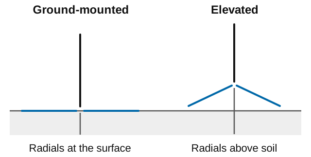
Radials give RF current a lower-loss path than the soil alone. More radials generally help, but their length, the soil, and the installation affect the benefit. Start with a practical design and add wires as space allows. Elevated verticals can use fewer carefully arranged radials, often two to four, because the wires provide the return system above the soil.
Fine-Tuning Your Vertical’s Match #
A quarter-wave vertical over an ideal ground plane has about 36 ohms of radiation resistance. This resistance represents power leaving as radio waves. At resonance, a low-loss vertical has a feed-point resistance close to that value—slightly below the 50 ohms most radios expect.
Key Information: To adjust the feed point impedance of an elevated quarter-wave ground-plane vertical antenna to be approximately 50 ohms, slope the radials downward.
Around 45 degrees downward is a common starting angle. Measure the match with the antenna in its intended position, then adjust as needed.
Sizing Your Vertical for Success #
A quarter-wave vertical (a monopole) is half the length of a half-wave dipole, so its starting-length formula uses half the factor: 234 instead of 468. The ground plane provides the other part of the antenna system.
Key Information: The approximate length for a 1/4 wave monopole antenna cut for 28.5 MHz is 8 feet.
Here the calculation is feet, a starting length to adjust for the installed antenna. An 8-foot vertical for 10 meters is much easier to fit into a small space than a full-size antenna for 80 meters. Higher bands can be a good place to start when space is limited.
Random Wire Antennas: The Compromise That Works #
Life doesn’t always provide perfect antenna locations. Maybe you’re in a neighborhood with antenna restrictions, renting, or need something temporary. A random-wire antenna uses a length of wire chosen to fit the available space, rather than cut to a specific resonant length. A tuner helps match it to the radio.
That wire still needs a return path for RF current. Without a suitable counterpoise or ground system, station equipment and connecting cables can become part of that path.
Key Information: A characteristic of a random-wire HF antenna connected directly to the transmitter is that station equipment may carry significant RF current.
This unwanted RF can make a microphone give you an RF burn or interfere with nearby electronics. A counterpoise provides a planned return path. A suitable choke can help keep unwanted current off connecting cables, while the tuner handles the impedance match. These parts work together; getting a low SWR alone doesn’t solve the return-path problem. With a suitable arrangement, a wire that fits your space can still make useful HF contacts.
NVIS: Your Regional Communication Powerhouse #
Earlier, we saw how a low dipole can favor nearby stations. That becomes useful during emergency nets or when you want to cover your state rather than work distant DX. Near Vertical Incidence Skywave (NVIS) uses signals sent nearly straight up and returned by the ionosphere to the surrounding region.
Key Information: A horizontal dipole antenna most effective as a Near Vertical Incidence Skywave (NVIS) antenna for short-skip communications on 40 meters during the day is one placed between 1/10 and 1/4 wavelength above the ground.
On 40 meters, that means mounting the dipole about 13–33 feet high. Think of an umbrella over the region: high-angle signals can return nearby when the ionosphere supports the frequency. This can help you reach stations beyond intervening hills, often within a few hundred miles. The next chapter explains how the frequency and ionosphere determine whether that path is available.
Practical Antenna Solutions #
General privileges include all nine HF amateur bands, but that doesn’t mean you need nine antennas. A fan dipole connects several dipoles of different lengths to one feed point, with each length serving a different band. Some end-fed designs also work on several bands, and the final section of this chapter explains another approach using antenna traps. A dipole fed with ladder line and a tuner can offer useful coverage across several bands too. Remember to allow space for routing the line clear of metal.
Limited space? Antennas shrink as frequency rises. A half-wave dipole that needs about 132 feet on 80 meters fits in about 16 feet on 10 meters. Small transmitting loops, shortened antennas with loading coils, and attic installations offer other options when a full-size outdoor antenna won’t fit.
Choose the height for the contacts you want: a high antenna for DX and a low NVIS antenna serve different paths. Use a suitable balun or choke where the design calls for one, check the SWR after installation, and weatherproof outdoor connections.
Remember, even modest antennas work DX when conditions cooperate. Focus on getting something in the air, then improve it over time. Your first antenna won’t be your last, but it will be the one that gets you started.
A dipole sends its strongest signal broadside in two directions. In the next section, we’ll see how adding elements can concentrate that energy into a beam.



 It is a figure-eight at right angles to the antenna