



Section 4.1: Feed Lines and Connectors #
You’ve just worked your first transatlantic contact. The European station gives you a “five by three” report—perfectly readable, but your signal is weak. You’re running 100 watts into what should be a decent antenna. Where did your power go?
As a Technician, you learned that impedance matching matters and that SWR tells you something about your antenna system. As you prepare to use more HF bands and perhaps longer feed line runs, you need to understand that “antenna system” isn’t just the antenna—it’s the complete chain from your radio through connectors, feed line, and finally to the antenna itself.
Understanding Characteristic Impedance #
Every feed line has a characteristic impedance determined by its physical construction. For ordinary low-loss RF cable, its rated impedance is nearly constant over its intended frequency range:
Key Information: The characteristic impedance of a parallel conductor feed line is determined by the distance between the centers of the conductors and the radius of the conductors.
The physics is beautifully simple:
- Spread conductors farther apart? Impedance goes up.
- Use fatter wires? Impedance goes down.
- What you connect to either end? Doesn’t change the cable’s characteristic impedance.
- Make the line longer or shorter? Its characteristic impedance stays the same.
Those comparisons assume the same insulating material, or dielectric, between the conductors. The dielectric also affects impedance.
Common impedances you’ll encounter:
- 50 ohms: The usual amateur radio standard—most transceivers expect it
- 75 ohms: Common in TV cable, but useful in some amateur installations too
- 450 ohms: Window line—spaced conductors and air gaps for low loss
This characteristic impedance is a fundamental property of the feed line itself. When you connect your radio (expecting 50 ohms) to 50-ohm coax and then to an antenna that also presents 50 ohms, power flows smoothly through the entire system. An impedance change along the feed line—at a connector, a splice between different lines, or the antenna—reflects some power. In a real feed line, the resulting standing waves can increase heat loss. We’ll explore those antenna mismatches in the next section. First, let’s compare the practical tradeoffs between feed-line types.
Key Information: The nominal characteristic impedance of “window line” transmission line is 450 ohms.
Window line (ladder line with rectangular cutouts) keeps loss low through its high impedance and mostly air dielectric. When matched, its higher impedance means less current for the same power, reducing heating in the wires. Those windows aren’t decorative—they reduce dielectric loss while maintaining conductor spacing.
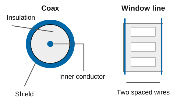
The tradeoff? Window line demands respect:
- Keep it away from metal objects
- Avoid sharp bends
- Protect it from ice buildup
- Keep sufficient clearance from other cables
Coax is the easygoing alternative—its shield confines the wanted signal and helps block outside interference. Unwanted current can still flow on the outside of that shield; Section 2.1 explains how a ferrite choke helps control it. Window line trades convenience for efficiency—worthwhile when you need every watt to count such as for QRP (low-power) operation.
Feed Line Loss: Where Your Power Goes #
Here’s a sobering thought: You might be losing more power in your feed line than you’re putting into your antenna. Every foot of cable between your radio and antenna acts like a resistor, converting your carefully generated RF into useless heat.
Key Information:
- The attenuation of coaxial cable increases with increasing frequency.
- RF feed line loss is usually expressed in decibels per 100 feet.
Three culprits steal your signal:
- Skin effect: At RF, current crowds onto the conductor’s surface. As frequency rises, this surface layer gets thinner and resistance increases.
- Dielectric heating: The insulation absorbs energy, especially as frequency climbs.
- Unwanted radiation: Damage or poor shielding can let coax leak RF. Open-wire or window line can also radiate if its currents become unbalanced, for example when it is routed too close to metal.
Let’s put this in perspective with RG-8X (a popular “compromise” cable). The Davis RF attenuation chart gives these figures:
- 10 MHz (30 meters): 0.78 dB/100 ft—barely noticeable
- 50 MHz (6 meters): 2.0 dB/100 ft—starting to hurt
- 200 MHz (VHF): 4.5 dB/100 ft—ouch!
- 400 MHz (UHF): 6.0 dB/100 ft—yikes!
These are specifications for one cable choice, not every product sold as RG-8X. Check the actual cable’s data at your operating frequency.
What does a 4.5 dB loss mean for your signal? At 200 MHz, send 100 watts through 100 feet of this cable and only about 35 watts reach your antenna. The other 65 watts? Warming up your coax. That could be part of why that distant station can’t hear you. And remember—this loss affects both transmit AND receive. Your signal weakens going out, and incoming signals weaken coming back in. It’s a double penalty. How much the receive loss hurts signal-to-noise ratio depends on the receiver and the external noise arriving with the signal.
Choosing Feed Line for Your Station #
Your choice depends on frequency, distance, power level, and installation constraints.
The Distance Factor: Running 10 feet to an attic antenna? For a short HF run, most sound 50-ohm coax will have little loss. Running 200 feet to that tower? Now feed line choice becomes critical. At HF, even mediocre coax might work for short runs, but those same losses multiply with distance until they dominate your signal budget.
HF and 160-Meter Operations: 160 meters is an MF band, though it is often grouped with HF in station discussions. Both window line and coax have their place. Window line offers extremely low loss—ideal for long runs or when you need maximum efficiency. But it requires careful installation away from metal, including other cables, tower legs, and rain gutters. You will often use a suitable antenna tuner, and ice or water can affect the line.
Quality coax trades some efficiency for convenience—it’s weather-resistant with properly sealed outdoor connections, is less affected by nearby metal, and connects directly to your radio. For most HF stations, good coax is the practical choice.
VHF/UHF Operations: Higher frequencies mean higher losses. Coax that works adequately at HF might lose half your power at 2 meters over a long run. At UHF you could see significant losses even with good coax. Short runs? Your existing cable may be fine if its ratings suit the job. For longer runs? Invest in better quality cable.
Power Considerations: QRP operators can use lighter coax—when you’re running 5 watts, power handling usually isn’t the main concern. But push 1500 watts through undersized coax and you risk damage from heating, especially with high SWR.
RF Connectors: Moving Beyond Handheld Adapters #
Once you’ve chosen the cable, you need suitable connectors at each end. For an HF station or a more demanding installation, connector choice becomes even more critical. The best radio and antenna in the world become expensive decorations if a poorly installed connector blocks your signal. A damaged PL-259, corroded connection, or wrong connector type can waste just as much power as having the wrong antenna.
Quick Review: The Connector Lineup #
You already know the basics—SMA for handhelds, UHF connectors (PL-259/SO-239) for mobile and base gear, BNC for quick connections. On HF, you’ll use these same connectors but sometimes in more demanding situations where details really matter.
BNC at HF Frequencies #
Key Information: A typical upper frequency limit for low SWR operation of 50-ohm BNC connectors is 4 GHz.
A suitable BNC connector can handle a 100-watt HF station; check the ratings of the actual connector and cable. You’ll see it on test equipment like antenna analyzers and oscilloscopes where the quick twist-lock connection is handy. Many HF transceivers and antennas come with UHF connectors, and BNC options for thick coax are more limited. Still, BNC is a useful choice on portable and test equipment.
Type N: An Underappreciated Option #
Key Information: A type N connector is a moisture-resistant RF connector useful to 10 GHz.
Type N has a lot going for it. It is highly weather-resistant, maintains a controlled impedance, and works into microwave frequencies. Many versions handle substantial HF power, but check the actual connector’s rating at your frequency before connecting an amplifier.
So why don’t we all use Type N? Simple: most amateur radio transceivers come with UHF connectors, so that’s what we use. Switching to Type N means adapters or replacing connectors, which adds hassle and potentially negates some benefits. Still, for permanent outdoor installations or VHF/UHF weak signal work, Type N is worth considering.
SMA: Small but Capable #
Key Information: An SMA connector is a small threaded connector suitable for signals up to several GHz.
Beyond handhelds, you’ll find these tiny threaded connectors on SDR equipment and compact test gear. Their main advantage is size—they pack impressive frequency handling into a connector barely larger than a pencil eraser.
Audio and Control Connections #
Key Information: RCA Phono connectors are commonly used for low frequency or DC signal connections to a transceiver.
Those RCA jacks behind your transceiver handle audio and control signals for digital modes, PTT keying, and external speakers. RCA connectors can also carry RF in some equipment, so check the labels.
Building Your Complete Antenna System #
Getting power to your antenna efficiently is only part of the story. What happens when that power arrives at the antenna? Does your antenna accept it, or does it reflect power back down the feed line, creating the standing waves you learned about as a Technician? That’s where impedance matching and SWR come into play—the critical final link in your antenna system that we’ll explore in the next section.


 The distance between the centers of the conductors and the radius of the conductors