



Section 3.4: Digital Signal Processing #
If you’ve ever compared a modern transceiver with an older analog radio, you may have noticed some differences. Modern radios are better able to make weak signals sound clearer and switch instantly between different filter types with the push of a button. They also offer features like automatic notch filtering that seem almost magical compared with the older radios. The key technology behind these capabilities is Digital Signal Processing (DSP)—which adds computer processing to the analog circuits still needed in a radio.
DSP Filters: Flexible Choices #
One of the most important DSP applications is advanced filtering:
Key Information: An advantage of DSP filters compared to analog filters is that a wide range of filter bandwidths and shapes can be created.
Traditional analog filters can be fixed, switched or adjustable. DSP makes a wide choice of responses practical by processing numerical samples of the signal mathematically. The same processing hardware can create a 200 Hz CW filter, a 2.8 kHz SSB filter, or many choices in between—just by changing the calculations. Providing all those choices with separate analog filters would require more components.
Choosing the Right Bandwidth #
Here’s a key principle for good reception:
Key Information: Matching receiver bandwidth to the operating mode gives the best signal-to-noise ratio.
Using the right bandwidth filter:
- Too wide: Admits unnecessary noise, reducing signal-to-noise ratio
- Too narrow: Can distort the signal, making it sound muffled or cutting off information
- Just right: Admits the wanted signal while rejecting noise outside its bandwidth
For example, a narrow CW signal does not need the broad passband used for voice. Narrowing that passband can exclude noise while retaining the CW signal. For a voice signal, however, too narrow a passband removes parts of the speech along with the noise.
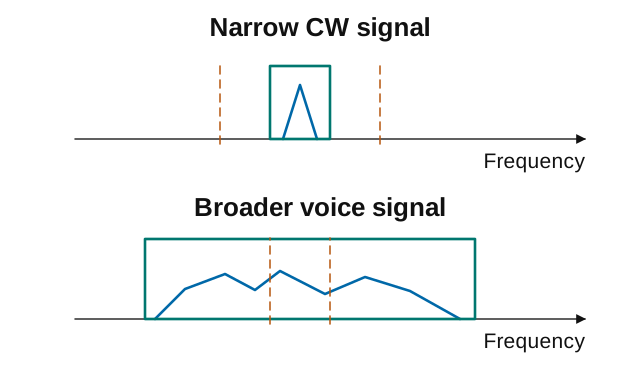
For a computer digital mode, the radio may pass a wider range containing several signals while the program filters each decoded signal narrowly. The radio’s passband and the decoder’s bandwidth need not be identical. Section 7.2 applies these choices to receiver controls.
Software-Defined Radio #
Key Information: Filtering, detection, and modulation are all functions performed by software in a software-defined radio.
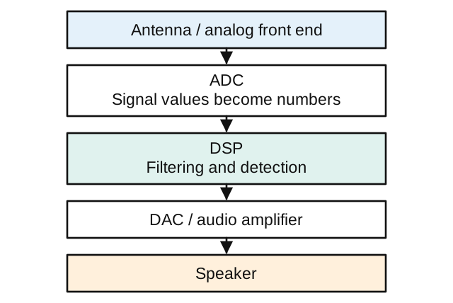
In Software-Defined Radio (SDR), software performs functions that otherwise would be fixed by circuit design. It is useful to picture a computer with an antenna input, but the physical radio still matters. An analog-to-digital converter (ADC) turns sampled signal values into numbers. Software can filter those values, detect the information they carry, or create modulation for a transmitter. A digital-to-analog converter (DAC) produces an analog output when needed, such as audio for a speaker. The radio still needs filters and amplifiers around those converters.
I and Q Signals: The Technical Foundation #
Modern DSP radios use a special technique involving I and Q signals:
Key Information:
- The phase difference between the I and Q RF signals that software-defined radio equipment uses for modulation and demodulation is 90 degrees.
- An advantage of using I-Q modulation with software-defined radios is that all types of modulation can be created with appropriate processing.
The “I” (in-phase) and “Q” (quadrature) components use reference directions 90 degrees apart. Remember our phase concepts from Section 1.2? The two streams of values tell us how much of each component is present; they are not necessarily identical copies of a waveform separated by a delay.
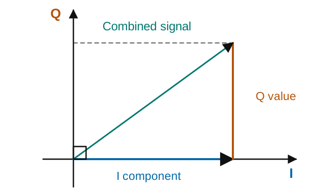
For example, a positive I value alone points along the I axis. Adding a positive Q value changes both the size and angle of the combined signal. Changing these values over time lets the radio control amplitude and phase.
By mathematically manipulating the I and Q signals, the same hardware can generate AM, FM, SSB, PSK, FSK, or other modulation types within its hardware capabilities. This is why modern transceivers can switch between modes instantly and support new digital modes through firmware updates.
Practical DSP Benefits #
DSP technology provides several advantages for amateur radio operation:
Adaptive Filtering: DSP filters can automatically adjust their characteristics, create multiple notches simultaneously, or track moving interference.
Noise Reduction: DSP can distinguish between noise and desired signals, often reducing some noise while preserving the signal you want to hear. An overly aggressive setting can distort wanted audio, and DSP cannot reliably restore information lost in an overloaded earlier stage.
Real-Time Analysis: Many DSP radios provide waterfall displays showing band activity and signal types visually.
DSP in Your General Class Operations #
For practical amateur radio use, DSP helps with:
- Weak signal work by extracting readable signals from difficult conditions
- Crowded band operation by filtering and suppressing interference
- Digital mode integration through built-in decoders
- Repeatable digital filter settings, though analog circuits can still drift with temperature or age



 A wide range of filter bandwidths and shapes can be created