



Section 2.4: Digital Circuit Fundamentals #
The switching power supplies in the previous section use transistors to turn current on and off. Digital circuits also use switching, but their purpose is to represent and process information. Inside your radio, these circuits handle tasks such as controlling settings and processing signals. To understand how they work, we’ll begin with two states: low and high.
The Digital Difference: Binary States #
Unlike analog circuits that work with continuously varying voltages and currents, digital logic represents information with two states: low or high (usually represented as 0 or 1). Each state allows a range of voltages; small noise changes within that range need not change the value. This binary approach creates circuits that are:
- More resistant to noise and interference
- Capable of precise, repeatable operations
- Able to perform complex logical functions
These reliable states let digital circuits carry out calculations on signal samples. That is the basis of digital signal processing, which we will explore in the next chapter.
Transistors as Switches #
Earlier in this chapter, we saw how a small base current controls a larger current in a bipolar transistor. Digital switching uses two operating conditions:
Key Information: A bipolar transistor used as a switch operates at cutoff and saturation.
In cutoff, very little collector current flows, like an open (off position) switch. In saturation, the collector-to-emitter voltage is small, like a closed (on position) switch. The load still limits the current. For example, a transistor can turn an indicator off in cutoff and on in saturation.
Logic Gates: Digital Decision Makers #
The fundamental building blocks of digital circuits are logic gates—components that perform basic decision-making functions based on their inputs:
Key Information: A two-input AND gate outputs a high signal (1) only when both inputs are high.
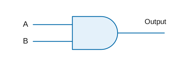
| A | B | Output |
|---|---|---|
| 0 | 0 | 0 |
| 0 | 1 | 0 |
| 1 | 0 | 0 |
| 1 | 1 | 1 |
Think of an AND gate as similar to a series circuit with two switches—both must be closed for current to flow. In digital terms:
- If Input A = 1 AND Input B = 1, then Output = 1
- For any other combination, Output = 0
Other basic gates include OR, NOT, NOR, NAND, and XOR.
Integrated Circuits: Technology in a Package #
Modern equipment uses integrated circuits (ICs) for most digital functions. These chips combine many circuit elements in one package, from small logic blocks to processors with millions of transistors.
MMICs: RF Processing in a Tiny Package #
Key Information: MMIC stands for Monolithic Microwave Integrated Circuit.
“Monolithic” means the circuit is formed together on one semiconductor chip. An MMIC can handle analog RF signals; being an IC does not make it digital. These specialized ICs are designed for radio frequency and microwave applications, integrating various RF functions into a single chip. Common examples include but are not limited to amplifiers, mixers, oscillators, and filters.
MMICs are a key reason why modern handhelds and mobile radios can offer sophisticated features in compact sizes.
CMOS vs. TTL: Digital Logic Families #
Digital ICs come in different “families” with distinct characteristics:
Key Information: An advantage of CMOS integrated circuits compared to TTL integrated circuits is low power consumption.
CMOS (Complementary Metal-Oxide-Semiconductor) can use very little power, especially when not switching. TTL stands for Transistor-Transistor Logic.
Check a device’s actual supply and input ratings before connecting logic families. CMOS switching still consumes energy, so faster and more complex chips can use substantial power. Modern amateur radio equipment widely uses CMOS technology due to its energy efficiency—particularly important for portable and battery-powered devices. This technology choice directly impacts your radio’s battery life and heat generation.
Operational Amplifiers: The Analog-Digital Bridge #
While we’re focusing on digital circuits, it’s important to understand how analog and digital circuits work together:
Key Information: An integrated circuit operational amplifier is an analog device.
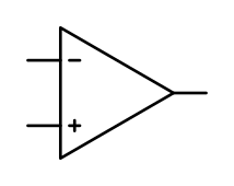
Operational amplifiers (op-amps) are versatile analog ICs that:
- Amplify and condition signals
- Create active filters
- Buffer between circuit stages
Op-amps often form the critical interface between analog signals (from antennas or microphones) and the digital processing systems within modern transceivers. They can prepare signals for an analog-to-digital converter and filter or buffer the output of a digital-to-analog converter. The converters perform the conversion; the op-amp remains an analog device.
Digital Storage and Processing Elements #
Digital circuits include specialized components for managing digital information:
Shift Registers: Digital Data Movement #
Key Information: A shift register is a clocked array of circuits that passes data in steps along the array.
A bit is one binary digit, 0 or 1. A clock provides the timing steps.
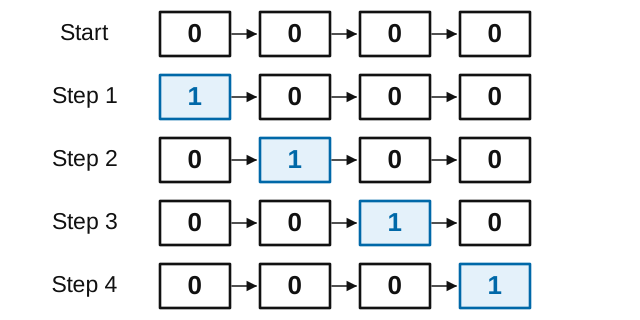
A shift register functions like a bucket brigade for digital data—each pulse of a clock signal moves the data one position down the line. This sequential movement is important for:
- Converting between serial and parallel data forms
- Creating precise timing delays
- Generating specific bit patterns
Shift registers are widely used for digital signal processing in modern transceivers and in the encoding/decoding circuits for digital communications modes.
Binary Counters: Tracking Digital States #
Key Information: A 3-bit binary counter has 8 states.
A binary counter is a digital circuit that advances through a sequence of binary states with each clock pulse. For a 3-bit counter:
| Decimal | Binary |
|---|---|
| 0 | 000 |
| 1 | 001 |
| 2 | 010 |
| 3 | 011 |
| 4 | 100 |
| 5 | 101 |
| 6 | 110 |
| 7 | 111 |
That’s different states: two possibilities for each of three bits. The largest value is seven because counting starts at zero.
Binary counters are fundamental to:
- Frequency synthesis in modern transceivers
- Digital frequency displays
- Timing and control functions
The number of bits in a counter determines how many states it can represent: different states for an n-bit counter. This exponential relationship is why adding just a few bits dramatically increases a digital system’s capabilities.
The Digital Foundation for Advanced Radio Features #
While we’ve focused on the fundamental components, these digital building blocks combine to create the sophisticated capabilities in modern equipment:
- Digital Signal Processing (DSP) uses these elements at high speeds to filter signals and reduce noise
- Software Defined Radio (SDR) uses digital processing to perform radio functions in software running on processing hardware, rather than in fixed analog circuits
- Digital Mode Operation relies on these components to encode and decode signals
When you use features like noise reduction, notch filters, or digital mode interfaces, you’re benefiting from these digital fundamentals working together.
Looking Ahead #
Analog and digital circuits both need a way to describe their connections and check their behavior. A schematic shows how the components fit together; a meter or waveform display lets you compare the working circuit with that description. Those are the two views we will connect in the next section.



 Saturation and cutoff