



Section 2.3: Power Supply Fundamentals #
Now that we’ve explored how transistors and tubes amplify signals, let’s turn our attention to what powers them. The active circuits in your radio need clean, stable DC power to operate properly. Your household outlets provide AC power, so we need a way to convert that alternating current into the direct current our radios require.
Whether you’re setting up a new station or trying to track down that annoying hum in your transmitted audio, these fundamentals will serve you well.
The Power Supply Journey: From AC to DC #
Converting AC from your wall outlet to clean DC for your radio involves these basic stages:
- Transformation - Changing the voltage level (if needed)
- Rectification - Converting AC to pulsating DC
- Filtering - Smoothing the pulses into steady DC
- Regulation - Maintaining constant voltage despite load changes
The previous chapter covered transformers and voltage ratios. We’ll start here with rectification, then follow the output through filtering and regulation.
Rectification: Converting AC to DC #
Rectification changes alternating current that flows back and forth into direct current that flows in one direction. There are two basic approaches to rectification: half-wave and full-wave.
Key Information:
- A half-wave rectifier converts 180 degrees of the AC cycle to DC.
- A full-wave rectifier converts 360 degrees of the AC cycle to DC.
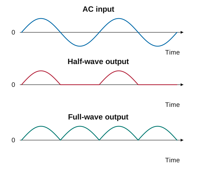
As you can see in the waveform comparison:
- The input AC signal alternates between positive and negative
- Half-wave rectification preserves only the positive portions, creating gaps in the output
- Full-wave rectification flips the negative portions to create a continuous series of positive pulses
Half-Wave Rectification #
Key Information: A half-wave rectifier is characterized by using only one diode.
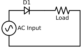
The half-wave rectifier is the simplest design:
- A single diode allows current to flow only during the positive half-cycle
- The diode completely blocks the negative half-cycle
- The output pulses occur at the same frequency as the input AC
Despite leaving half of each AC cycle unused, half-wave rectification is sometimes used in:
- Simple battery chargers
- Power indicators
- Applications where cost and simplicity outweigh efficiency concerns
- Circuits where only a small amount of DC power is needed
Full-Wave Rectification #
Full-wave rectifiers utilize the entire AC cycle, making them more efficient and easier to filter.
Key Information: An unfiltered full-wave rectifier connected to a resistive load produces a series of DC pulses at twice the frequency of the AC input.
The main advantage of full-wave rectification is its efficiency:
- It utilizes both positive and negative portions of the AC cycle instead of skipping alternate half-cycles
- By converting both halves of the cycle, it inherently produces pulses at twice the input frequency (120 Hz from a 60 Hz input)
- The unfiltered output still reaches zero, but the shorter time between peaks makes filtering easier for a given load and capacitance
The exam covers two common full-wave rectifier designs: center-tapped transformer and bridge rectifier.
Center-Tapped Transformer Design #
Key Information: A full-wave rectifier circuit using a center-tapped transformer uses two diodes.
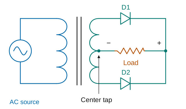
This design uses:
- A transformer with a center tap on its secondary winding
- Two diodes that alternately conduct during opposite half-cycles
- The center tap serves as the common (often ground) connection
During operation:
- When the top of the secondary is positive relative to the center tap, the top diode conducts
- When the bottom of the secondary is positive relative to the center tap, the bottom diode conducts
- In both cases, current flows in the same direction through the load
Bridge Rectifier Design #
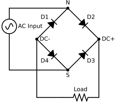
The bridge rectifier uses four diodes arranged to:
- Direct current through the load in the same direction regardless of input polarity
- Eliminate the need for a center-tapped transformer
The AC connections in the diagram are marked N (top) and S (bottom). We’ll use the “positive to negative” convention of tracing current flow.
- When N is positive, current flows from
N->D2->DC+->Load->DC-->D4->S - When N is negative, current flows from
S->D3->DC+->Load->DC-->D1->N
Center-tapped vs. Bridge Rectifier Designs #
Each design has advantages and disadvantages:
Center-tapped transformer design:
- Uses fewer components (only two diodes)
- Only one diode voltage drop in the current path
- Requires a special center-tapped transformer
- Less efficient use of the transformer (each half of the secondary winding conducts only 50% of the time)
Bridge rectifier design:
- Works with a suitable transformer without needing a center tap
- More efficient use of transformer windings
- Requires four diodes instead of two
- Two diode voltage drops in series (higher loss)
Rectifier Voltage Drops #
In practical circuits, the diode forward voltage drop affects the output. For a rough calculation, use about 0.7V per conducting silicon junction diode; the actual drop depends on device, current and temperature. This means:
- In half-wave rectifiers: output is reduced by about 0.7V
- In center-tapped designs: output is reduced by about 0.7V
- In bridge rectifiers: output is reduced by about 1.4V (two diodes in series)
For high-power applications, this voltage drop represents wasted power and heat generation in the diodes.
Most amateur radio power supplies use full-wave rectification for its efficiency and easier filtering. Bridge rectifiers are the most common in modern designs because of their flexibility and the low cost of diodes.
Filtering: Smoothing the Pulses #
Rectification alone produces pulsating DC—not the smooth, constant voltage our radio equipment needs. The next step is filtering, which smooths these pulses into steady DC.
Key Information: Capacitors and inductors are used in a power supply filter network.
The most common filter configuration uses large electrolytic capacitors that charge during voltage peaks and discharge during valleys, filling in the gaps to create smoother DC. In filter circuits, inductors can resist current changes and further smooth the output.
Think of filter capacitors like water towers in a municipal water system. High pressure (voltage) refills the tower near each peak. Between peaks, the tower keeps the pressure up while the town draws water (current). The larger the capacitor, the more energy it can store and the smoother the output becomes.
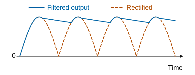
The small repeated rise and fall left in the filtered output is called ripple. Too much ripple can cause hum in your audio.
A regulator adjusts the supply’s operation to keep its output voltage close to the desired value as input voltage or load current changes. Filtering smooths the pulses; regulation controls the output level.
Safety: Bleeder Resistors #
When you turn off a power supply, those large filter capacitors can retain dangerous charges for minutes or even hours. This creates a serious shock hazard for anyone working on the equipment.
Key Information: A power supply bleeder resistor discharges the filter capacitors when power is removed.
Bleeder resistors are high-value resistors connected across the filter capacitors. They provide a discharge path that safely drains stored energy when the power supply is turned off. While they do consume a small amount of power during operation, the safety benefit far outweighs this minor inefficiency.
Never assume a power supply is safe just because it’s unplugged! Those capacitors can deliver a painful or even dangerous shock. A bleeder can fail or be absent, so waiting alone does not prove the supply safe. Follow the equipment’s service procedure and have stored voltage checked before internal work. Chapter 6 covers electrical hazards.
Modern Alternative: Switchmode Power Supplies #
The transformer, rectifier, filter, and regulator we have followed make up a traditional linear power supply. These supplies work well but tend to be large and heavy due to their 60 Hz transformers and massive filter capacitors. Switchmode (switching) power supplies offer a more compact alternative.
Key Information: High-frequency operation allows switchmode power supplies to use smaller components compared to linear power supplies.
Instead of transforming 60 Hz AC directly, a typical switchmode supply that runs from household AC and provides electrical isolation will:
- Rectify the incoming AC to DC
- Use high-speed switching transistors to create high-frequency AC
- Transform this high-frequency AC to the desired voltage
- Rectify and filter the output
Because transformers and filter components can be much smaller at higher frequencies, switchmode supplies achieve the same power output in a fraction of the size and weight. This is why switching supplies are common in radio stations despite their increased complexity.
The tradeoff? Switchmode supplies can generate RF interference due to their high-frequency switching. Good design and shielding minimize this issue, but it’s something to consider when choosing between linear and switching supplies for your station.
Next, we’ll explore digital circuits and see how modern radios use digital technology to enhance performance.


 180 degrees