

Section 2.2: Transistors and Amplification #
A typical transmitter starts with a low-power RF signal. Before that signal reaches the antenna, amplifiers raise it to the desired output power. This happens inside a handheld or HF radio; adding a separate power amplifier gives the signal another boost. Receivers also use amplifiers to strengthen weak signals and produce sound from a speaker.
To do that, an amplifier uses a small input signal to control a larger current from a battery or power supply. Transistors and vacuum tubes provide that control.
Transistors: The Building Blocks of Amplification #
Transistors are semiconductor devices that can amplify signals or switch current on and off. The two main types are bipolar junction transistors and field-effect transistors. They differ in how they control current.
Bipolar Junction Transistors (BJTs) #
Bipolar transistors consist of three semiconductor layers (collector, base, and emitter). A small current through the base controls a much larger current between collector and emitter.
Later in this chapter, we’ll use that same control for digital switching, where the transistor operates at cutoff and saturation.
Field-Effect Transistors (FETs) #
FETs use an electric field from a control terminal called the gate to control current through a semiconductor channel. One type is the MOSFET, or metal-oxide-semiconductor field-effect transistor.
Key Information: In MOSFET construction, the gate is separated from the channel by a thin insulating layer.
This insulating layer creates an extremely high input impedance, as virtually no steady DC current flows into the gate. Charging and discharging the gate’s capacitance still requires current when its voltage changes. The voltage at the gate creates an electric field that controls current flow between the source and drain.
Both transistor types have important roles in your radio. Bipolar transistors are often used in audio and low-level RF stages, while MOSFETs are common in RF power amplifiers and some receiver front ends.
Vacuum Tubes: Understanding Legacy Technology #
Though largely replaced by solid-state devices in modern equipment, vacuum tubes remain important to understand. You’ll find them on your exam and in older equipment still in use. Manufacturers still make them for specific applications like high-power RF amplifiers. Tubes perform much the same function that we now usually use transistors for, and suitable tube designs can handle high voltages and power levels.
Vacuum tubes work by controlling a stream of electrons flowing from a heated cathode to a plate (anode) through a vacuum.
Key Information:
- The control grid in a vacuum tube regulates the flow of electrons between cathode and plate.
- The primary purpose of a screen grid in a vacuum tube is to reduce grid-to-plate capacitance.
The control grid acts like a gate, varying electron flow based on its voltage. Small voltage changes on the grid cause large changes in plate current, providing amplification.
The screen grid sits between the control grid and plate, reducing capacitance between them. Lower capacitance means less feedback from output to input, helping prevent unwanted oscillation in RF amplifiers.
While most new amateur radio equipment uses solid-state technology (transistors), tubes are still found in:
- Some commercial and amateur high-power amplifiers
- Vintage equipment that many hams still enjoy using
- Specialty audio equipment where some prefer their characteristics
Amplifier Classes: Efficiency vs. Fidelity #
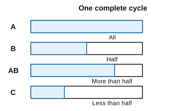
Amplifier “classes” (A, B, AB, C) describe when a transistor or tube conducts current during a signal’s waveform cycle. These classes reflect a tradeoff all amplifiers face between efficiency and signal fidelity—how faithfully the output reproduces the input signal.
Amplifier Efficiency #
Key Information: The efficiency of an RF power amplifier is determined by dividing the RF output power by the DC input power.
For example, if an amplifier draws 200 watts from your power supply but produces only 100 watts of RF output, its efficiency is ( ). The remaining power becomes heat, which explains why some amplifiers need cooling fans.
Efficiency varies with the circuit, signal and output level; a class name does not specify one fixed percentage. The classes below describe how much of each cycle the device conducts.
Amplifier Linearity #
Key Information: A linear amplifier preserves the input waveform in the output.
Linearity refers to how faithfully an amplifier reproduces its input signal. In a perfectly linear amplifier, the output is an exact (but larger) copy of the input. This is crucial for modes where the signal’s shape contains information, such as SSB voice operation, AM signals, and digital modes such as PSK31.
Now let’s look at the main amplifier classes:
Class A Amplifiers: Maximum Fidelity
#
Key Information: In a Class
Aamplifier, the amplifying device conducts current 100% of the time.
Class A amplifiers can provide excellent linearity, but their efficiency is relatively low. The device conducts during the entire waveform cycle and, within its operating limits, can faithfully reproduce the input. You’ll find Class A amplification in receiver front ends and low-level stages where signal accuracy is crucial.
Class C Amplifiers: Maximum Efficiency
#
Key Information:
- Class C amplifiers have the highest efficiency of these classes.
- A Class C power stage is appropriate for amplifying FM signals.
Class C amplifiers conduct for less than 50% of the waveform cycle, achieving high efficiency but not preserving a changing amplitude envelope. A tuned output circuit turns the device’s current pulses into a sinusoidal RF output.
Since FM encodes information in frequency rather than amplitude, the distortion introduced by Class C doesn’t affect the information content, making it ideal for FM transmitters.
Class B and AB: The Middle Ground
#
Class B (50% conduction) and Class AB (more than 50% but less than 100% conduction) offer a compromise between efficiency and linearity. Most SSB transmitters use Class AB in their final stages to balance reasonable efficiency with acceptable linearity.
Oscillators: Signal Generators #
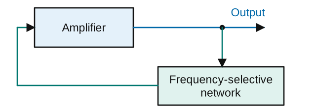
An amplifier can also help generate a signal. With the right feedback and frequency selection, it becomes part of an oscillator. Oscillators provide the RF signals used in transmitters and for frequency conversion in receivers:
Key Information: The basic components of a sine wave oscillator are a filter and an amplifier operating in a feedback loop.
An oscillator needs three elements:
- Amplification to overcome losses
- Frequency selection (filtering)
- Positive feedback that reinforces the oscillation
Many oscillators use an LC (inductor-capacitor) tank circuit to select the frequency. As we saw in the previous chapter, its inductance and capacitance determine that frequency.
Modern transceivers often use direct digital synthesis (DDS) for frequency generation. DDS systems use digital techniques to generate analog waveforms, providing fast frequency changes with excellent stability.
Key Information: A direct digital synthesizer (DDS) is characterized by variable output frequency with the stability of a crystal oscillator.
A crystal-controlled reference clock times the digital sequence. Changing that sequence selects a different output frequency while retaining the clock’s stable time reference.
Amplifier Stability #
The feedback that makes an oscillator work can cause trouble in an ordinary amplifier:
Key Information: The purpose of neutralizing an amplifier is to eliminate self-oscillations.
Self-oscillation occurs when some of an amplifier’s output feeds back to its input in the right phase to create a feedback loop. Neutralization techniques cancel out this unwanted feedback, typically by feeding back an equal but opposite signal.
Whether you’re selecting a linear amplifier for SSB operation or troubleshooting an oscillation problem, these concepts provide valuable insights.
Next, we’ll explore how power supplies convert household electricity into the steady DC voltages your radio equipment requires.



 The gate is separated from the channel by a thin insulating layer