



Section 2.1: Essential RF Components #
Remember those basic electronic components from your Technician studies? At radio frequencies, especially on HF bands, they behave in surprising ways! That capacitor working perfectly in an audio circuit might be useless in an RF filter. A simple resistor could suddenly act like an unwanted inductor.
Understanding these RF behaviors helps explain why antennas work better on some bands than others and how your transceiver separates one signal from thousands.
Diodes: More Than Just One-Way Streets #
In your Technician studies, you learned that diodes act like one-way streets for current. At RF frequencies, they perform even more interesting tricks!
Forward Threshold Voltage #
A diode is like a one-way gate, with voltage providing the push to open it. A small forward voltage opens the gate only a crack, letting a tiny trickle of current through. Near the diode’s forward threshold voltage, the gate effectively swings wide open. The rest of the circuit then limits how much current flows.
Different diode types have different approximate forward thresholds:
Key Information:
- The approximate forward threshold voltage of a germanium diode is 0.3 volts.
- The approximate forward threshold voltage of a silicon junction diode is 0.7 volts.
Signals from an antenna can be tiny. Germanium diodes and suitable Schottky diodes conduct at low forward voltages, making them useful in detectors that recover speech or music from AM signals. Detection can happen even below the usual threshold, where the gate is open only a crack.
With a good antenna and a sensitive earphone, a crystal radio can let you hear a strong local AM station without a battery or amplifier. The received signal itself supplies the energy.
Capacitors: Choosing the Right Type for RF #
You might remember from your Technician studies that capacitors store energy in electric fields and block DC while passing AC. At radio frequencies, the type of capacitor you use becomes critical.
Key Information:
- Electrolytic capacitors are characterized by high capacitance for a given volume (size).
- Low voltage ceramic capacitors are characterized by comparatively low cost.
While electrolytic capacitors pack impressive capacitance into small spaces, they have significant limitations at radio frequencies. Most are polarized, which means the voltage across them must have the marked polarity. That is different from requiring current to flow in only one direction! A power-supply capacitor charges and discharges, so its current reverses while its positive terminal can remain at the higher voltage.
If the voltage itself reverses, it is applied in the wrong direction and can damage the capacitor. There is no general 1–2 V reverse-voltage allowance to treat as safe. Follow the manufacturer’s voltage and ripple-current ratings; the ripple-current rating tells you how much charging and discharging current the capacitor can handle.
Electrolytic capacitors also have internal resistance and inductance, which can limit their effectiveness at radio frequencies. Think of them like water towers—great for storing large amounts, but slow to respond to rapid changes. This is why your transceiver uses electrolytic capacitors mainly for power supply filtering, where they handle relatively slow changes in DC voltage.
For most RF applications, ceramic capacitors are the better choice. They’re non-polarized (either voltage polarity is allowed) and inexpensive. Suitable types respond well to the rapid changes of RF signals. This is why your transceiver contains so many ceramic capacitors in its RF circuits for filtering, tuning, and coupling signals between stages.
Inductors and Ferrites: Magnetic Field Masters #
Inductors (coils) are essential in RF circuits, helping to filter signals, match impedances, and form resonant circuits with capacitors. At RF, the material inside a coil dramatically affects its performance.
Ferrite Cores: Frequency-Selective Materials #
Key Information: The performance of a ferrite core at different frequencies is determined by the composition, or “mix,” of materials used.
Ferrite cores aren’t “one-size-fits-all”—manufacturers formulate them specifically for different frequency ranges. It’s like having different grades of tires for different road conditions.
A ferrite core that works beautifully at 3.5 MHz might be terrible at 28 MHz because of its composition. Manufacturers offer various “mixes” (like Type 43, Type 61, etc.) optimized for specific bands. When you buy ferrite beads or cores for interference problems, getting the correct mix can make a big difference.
Toroidal Inductors: Donut-Shaped Wonders #
Key Information: Advantages of using a ferrite core toroidal inductor include: large values of inductance may be obtained, the magnetic properties of the core may be optimized for a specific range of frequencies, and most of the magnetic field is contained in the core.
Those donut-shaped ferrite cores you see in filters and antenna tuners offer significant advantages for RF applications:
- Self-shielding: Keeping most of the magnetic field within the core reduces unwanted coupling with nearby components
- Compactness: Higher inductance values in smaller spaces
- Customization: Different mixes for different frequency ranges
A Coil’s Self-Resonant Frequency #
There is another RF behavior to watch for: adjacent turns of a coil have a small capacitance between them. Even though you did not install a separate capacitor, this stray capacitance and the coil’s inductance form a resonant circuit.
Key Information: Above its self-resonant frequency, an inductor becomes capacitive.
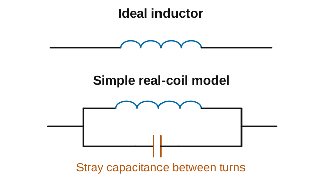
For example, an RF choke with self-resonance below your operating frequency may not provide the increasing inductive reactance you expect. Check its behavior at the frequency you need, not just the inductance marked on the part.
Ferrite Beads: RF Interference Fighters #
Have you ever noticed that many computer cables have a cylindrical bulge near one end? Those are ferrite beads!
Key Information: A ferrite bead or core reduces common-mode RF current on the shield of a coaxial cable by creating an impedance in the current’s path.
On coax, the desired signal current travels along the center conductor and returns along the inside of the shield. Those equal and opposite currents largely cancel their magnetic effects in a ferrite around the whole cable. Unwanted common-mode current on the outside of the shield does not have that cancellation. It encounters the ferrite’s impedance, which can include both reactance and loss, while the desired signal is affected much less.
In amateur radio, we use ferrites to prevent RF interference in audio equipment, computer connections, and antenna feed lines. Different ferrite “mixes” are formulated to work best at specific frequency ranges.
Resistors: Not All Types Work at RF #
Resistors seem simple, but at RF frequencies, their construction becomes critical:
Key Information: Wire-wound resistors should not be used in RF circuits because the resistor’s inductance could make circuit performance unpredictable.
Wire-wound resistors are exactly what they sound like—wire wound around a form to create resistance. This winding creates an inductor along with the resistor—a hidden component that can cause havoc in RF circuits.
For RF work, suitable carbon composition, metal film, or specialized RF resistors are better choices because they minimize unwanted inductance. Check the part’s RF specifications.
LEDs: Light-Emitting Diodes #
Key Information: An LED is forward biased when emitting light.
“Forward biased” means voltage is applied in the correct direction—positive to the anode and negative to the cathode. On many through-hole LEDs, the anode has the longer lead. If the leads have been trimmed or the LED uses another package, check the markings or specifications. Unlike incandescent bulbs, LEDs only work when connected with the proper polarity. They also need current limiting, often a series resistor. This isn’t specific to RF, but it’s on the exam and important when using LEDs in station accessories or projects.
RF Components in Action #
The differences in how components behave at RF frequencies explain many everyday amateur radio experiences. When your antenna matches well on 40 meters but not on 15 meters, you’re seeing frequency-dependent reactance in action. When ferrites on a cable eliminate the RF noise in your speaker, you’re witnessing the selective blocking of common-mode currents.
These components can direct current, filter signals, and store energy. Making a signal more powerful takes an additional source of energy, such as a battery or power supply. An amplifier uses that energy to strengthen the signal.



 0.3 volts