



Section 1.2: Reactance and Impedance #
In the previous section, we combined capacitors and inductors to find their total values. Those values can stay the same while their opposition to AC changes with frequency. We call this frequency-dependent opposition reactance. Resistance and reactance together determine impedance, the total opposition to current in an AC circuit. Reactance also affects the timing between voltage and current, which brings us to phase.
Why AC Circuits Are Different: The Phase Concept #
Imagine a spinning wheel. As the wheel turns, a point on its edge moves in a circle, completing a full rotation. Each rotation is a “cycle.”

- Phase tells us where a point is in its rotation. We measure phase in degrees (a full circle is 360°).
- For this discussion, we use sine-wave AC and ideal components. Real signals can have other shapes.
- If voltage and current rise and fall together, they are “in phase.”
- When current peaks at a different time than voltage, they are “out of phase.”
Reactance: Opposition Beyond Resistance #
Unlike resistance, which simply converts electrical energy to heat, reactance temporarily stores energy and then returns it to the circuit. This energy storage creates a phase shift between voltage and current.
Key Information:
- Reactance is opposition to the flow of alternating current caused by capacitance or inductance.
- The letter X represents reactance
- We measure reactance in ohms (Ω)
There are two types, each with unique behaviors:
Inductive Reactance #
Key Information:
- Inductive reactance is opposition to the flow of alternating current in an inductor.
- As the frequency of applied AC increases, inductive reactance increases.
An inductor’s changing magnetic field produces a voltage that opposes changes in current. In an ideal inductor, current lags 90° behind voltage.
An inductor’s reactance depends on frequency. Think of an inductor as increasingly “stubborn” about changing current flow as frequency rises. This makes inductors useful as RF chokes that block high frequencies while passing DC and low frequencies.
Practical Application: When you see an RF choke in an antenna feed line or a ferrite bead on a computer cable, you’re seeing impedance at work—opposing unwanted RF currents while allowing desired currents to pass. Ferrites can provide both reactance and loss; the next chapter’s discussion of RF components explains how those help suppress interference.
Capacitive Reactance #
Key Information:
- Capacitive reactance is opposition to the flow of alternating current in a capacitor.
- As the frequency of applied AC increases, capacitive reactance decreases.
Capacitors resist changes in voltage by storing energy in an electric field. In an ideal capacitor, current leads voltage by 90°.
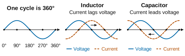
A capacitor’s reactance also depends on frequency, but in the opposite way from inductors. Capacitors become more “willing” to pass current as frequency rises. This makes them excellent as bypass capacitors that provide an easy path for RF signals while blocking DC.
Impedance: The Complete Picture #
Real-world radio circuits generally contain both resistance and reactance. We call their combined effect impedance.
Remember Ohm’s law from your Technician studies? For DC circuits, resistance equals voltage divided by current: . This fundamental relationship doesn’t change for AC circuits—we just need to account for the phase shifts that reactance causes.
Key Information: Impedance is the ratio of voltage to current in an AC circuit.
So while Ohm’s law for DC circuits states , the AC version uses impedance: . Impedance (Z) represents the total opposition to current flow, and we still measure it in ohms (Ω), just like resistance. The key difference is that impedance includes both magnitude and phase relationships.
We can combine resistance and reactance mathematically to find impedance, but they do not add like ordinary numbers. An antenna analyzer may show resistance and reactance separately, or the impedance magnitude—the size of the total opposition.
Why Impedance Matters: Impedance is crucial because it determines how efficiently power transfers between components. Matching accounts for both resistance and reactance—a principle central to antenna systems, feed lines, and amplifier design. Later in this chapter, we’ll examine the matching conditions and the usual 50-ohm equipment requirement.
Admittance: The Inverse Perspective #
While impedance is the primary way we describe AC opposition, engineers often find it mathematically convenient to work with its inverse, especially when analyzing parallel circuits:
Key Information: Admittance is the inverse of impedance.
Just as conductance is the inverse of resistance, admittance (Y) is the inverse of impedance:
We measure admittance in siemens (S), and it is particularly useful when analyzing parallel circuits. When components are in parallel, their admittances simply add together, making calculations much simpler than working with impedances directly.
Introducing Resonance: A Special Case #
The opposing behaviors of inductors and capacitors create a fascinating scenario when you combine them in a circuit:
Key Information:
- In a series LC circuit at resonance, impedance is very low
- At resonance, inductive reactance and capacitive reactance are equal and cancel each other
Since inductive reactance increases with frequency while capacitive reactance decreases, a simple ideal LC circuit has one frequency where they’re equal—the resonant frequency.
We’ll explore what happens at resonance in the next section. Resonance is the foundation for filters that select desired frequencies, oscillators that generate signals, antennas tuned for particular bands, and impedance matching networks.
Making Sense of Your Equipment #
An antenna also has resistance and reactance. Its impedance can change with frequency, changing the SWR even though the antenna hasn’t moved. Ferrite cores reduce interference because their impedance can include both reactance and loss. Bypass capacitors clean up power supplies by offering low capacitive reactance to noise.
Most importantly, you’re ready to understand resonance—that special frequency where inductive and capacitive reactances cancel completely.


 Opposition to the flow of alternating current caused by capacitance or inductance