

Section 1.1: Series and Parallel Circuits #
Did you ever use those old Christmas lights where one burned-out bulb killed the whole string? That’s an example of a series circuit—components connected end-to-end in a single path. Now think about the outlets in your home: unplug the lamp and your radio keeps playing. That’s a parallel circuit—each device has its own path to power.
Parallel capacitors add together for more filtering, but series capacitors actually decrease in total value. Understanding why components combine differently in series versus parallel helps you make sense of circuits throughout your station, from filters to antenna matching networks.
Understanding Current and Voltage in Series and Parallel Circuits #
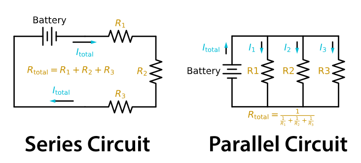
We can visualize electricity like water flowing through pipes. Let’s take a look:
Series Circuits: #
In series circuits, imagine garden hoses connected end-to-end: every drop must flow through each section in sequence. Every bit of current that goes in one end has to pass through every part of the hose (circuit), so current stays the same everywhere. The pressure (voltage) drops across restrictions in the path. In our circuit, the resistors provide those restrictions. We treat the wires and connections as having negligible resistance, so almost all the voltage drop is across the resistors.
- One Path: Components connected end-to-end in a single loop—current must flow through each in turn.
- Same Current Everywhere: Like our garden hose example, the same current flows through every component.
- Voltage Divides: Total voltage splits among components. Each creates a voltage drop; all drops sum to source voltage.
- Ohm’s Law: Since current is constant, voltage drop depends on resistance: . Higher resistance means a larger voltage drop.
- Failure Modes: An open component, such as a burned-out bulb, breaks the path and stops current flow. A short bypasses a component’s normal resistance; with the same source voltage, more current flows through the remaining resistors.
Parallel Circuits: #
With a parallel circuit it’s more like your home’s plumbing, where the main line branches to different rooms. Each branch gets the full house pressure (same voltage), but only some of the current flows to each part of the house (current divides). Close one valve and the others keep flowing.
- Multiple Paths: Components connected side-by-side—current can flow through any branch.
- Same Voltage Everywhere: Like home plumbing, each branch gets full source voltage.
- Current Divides: Total current splits among branches based on resistance. Branch currents sum to total current.
Key Information: In a circuit of parallel resistors, the total current equals the sum of the currents through each branch.
- Ohm’s Law: Since voltage is constant, current through each branch depends on its resistance: . Lower resistance means more current.
- Independent Operation: One branch opens, others continue—like your home outlets working independently. A shorted branch is different: it can overload the shared supply or trip its protection.
How Different Components Combine #
Now that we understand current and voltage behavior, let’s see how components combine. We’ll cover this in more detail below, but here is the short version:
| Component | Series Connection | Parallel Connection |
|---|---|---|
| Resistors | Direct Sum: | Reciprocal Method: |
| Capacitors | Reciprocal Method: | Direct Sum: |
| Inductors | Direct Sum: | Reciprocal Method: |
Memory tip: Resistors and inductors follow the same rules (add in series, reciprocal in parallel). Capacitors flip the pattern—they add in parallel because parallel plates mean more storage area. Now let’s explore each type with practical examples.
Resistors in Combination #
When resistors are in series, their values add. When resistors are in parallel, the total resistance is always less than the smallest resistor in the group.
Resistors in Series (Direct Sum Method): #
When resistors are connected end-to-end, their values simply add:
Think of it like adding garden hose sections—more length means more resistance.
Resistors in Parallel (Reciprocal Method): #
Each parallel resistor adds a path for current. More total current flows at the same voltage, which means less total resistance. To find it, use the reciprocal rule from the table above. For just two resistors, we can simplify to:
Let’s look at some problems you could encounter on your exam:
What is the total resistance of a 10-ohm, a 20-ohm, and a 50-ohm resistor connected in parallel?
Notice how 5.9 Ω is less than our smallest resistor (10 Ω)? This is ALWAYS true for parallel resistors—a great way to check your work!
For a simpler example:
What is the approximate total resistance of a 100-ohm and a 200-ohm resistor in parallel?
Capacitors in Combination #
Remember, a capacitor is just two conductors (usually metal plates) separated by an insulator (the dielectric). Capacitance measures how much charge a capacitor stores per volt. It depends on plate area—bigger plates can store more charge. When you connect capacitors in parallel, you’re essentially combining their plate areas into one larger capacitor. In series, each capacitor stores the same amount of charge, but their voltage drops add. Storing that charge takes more total voltage, so the combined capacitance is lower. That explains why capacitors combine opposite to resistors.
Key Information: To increase the total capacitance in a circuit, add a capacitor in parallel.
Capacitors in Parallel (Direct Sum Method): #
When capacitors are connected in parallel, their values add:
Think of parallel capacitors like joining storage tanks—you get more total capacity.
Capacitors in Series (Reciprocal Method): #
For capacitors in series, we use:
For two capacitors, we can simplify to:
The result is less than the smallest individual capacitance—another useful way to check your work.
What is the equivalent capacitance of two 5.0-nanofarad capacitors and one 750-picofarad capacitor connected in parallel?
Since capacitors in parallel add directly, we just need to convert to the same unit (750 pF = 0.75 nF) and add:
What is the capacitance of three 100-microfarad capacitors connected in series?
Another common example:
What is the capacitance of a 20-microfarad capacitor connected in series with a 50-microfarad capacitor?
Inductors in Combination #
Inductors store energy in magnetic fields and follow rules similar to resistors.
Key Information: To increase the total inductance in a circuit, add an inductor in series.
Inductors in Series (Direct Sum Method): #
When inductors are connected in series (and are not magnetically coupled), their values add:
Inductors in Parallel (Reciprocal Method): #
For inductors in parallel (assuming no magnetic coupling), we use:
Note: These formulas assume the inductors are physically separated so their magnetic fields don’t interact. When inductors do couple magnetically (like in transformers), different principles apply—you’ll see this concept in action later in this chapter.
What is the inductance of a circuit with a 20-mH inductor connected in series with a 50-mH inductor?
What is the inductance of three 10-mH inductors connected in parallel?
Connecting to Real Amateur Radio Applications #
These calculations aren’t just exam prep—they’re tools that help you understand what your equipment is doing. Here are a few examples of where you’ll see these principles in action:
- Resonant Circuits: Variable capacitors parallel with inductors tune to specific frequencies
- Impedance Matching: Antenna tuners can combine inductors and capacitors in series and parallel arrangements to present a 50Ω load to the transmitter
- Filtering: One low-pass filter design uses inductors in line with the signal to oppose higher frequencies and capacitors from the signal line to ground to bypass them
- Power Distribution: For resistive DC loads, the same current flows through each series resistor ( ), while each parallel resistor has the same voltage across it ( )
Your Foundation Is Set #
You can predict how current divides in parallel branches and how voltage divides across series components. You know why parallel resistors always give you less resistance than the smallest one in the group.
But here’s the plot twist: even when capacitance and inductance stay the same, their opposition to current changes with AC frequency. This special kind of opposition opens new possibilities for filtering, tuning, and matching.




 It equals the sum of the currents through each branch