

Section 9.3: Finding Noise and Interference #
Switch nearby devices off one at a time, where you safely can, and a noise coming from one of them stops when you reach it. That slow search is the standard method, and the noise itself can shorten it. Its spacing across the dial, its rhythm, and when it comes and goes all point toward likely causes, though each clue still needs a test.
Listen for a Pattern #
Evenly spaced signals suggest a source that repeats. A switch-mode power supply switches at a steady rate, and its harmonics fall at every multiple of that rate, evenly spaced far up the spectrum. Network equipment behaves differently. Its clocks and data links run at a few set rates, and the traffic they carry changes from moment to moment.
Key Information:
- Switch-mode power supplies can cause a series of carriers at regular intervals across a wide frequency range.
- Computer network equipment can produce unstable modulated or unmodulated signals at specific frequencies.
Intermittent roaring or buzzing on the AC line points to a different family of causes: arcing, where current jumps a small gap. Switch contacts can arc each time they open or close. A failing transformer can arc inside, and so can worn insulation or connections in high-voltage lighting such as neon. A failing part may also behave differently as it warms.
Key Information: Intermittent loud roaring or buzzing AC line interference can come from arcing contacts in a thermostatically controlled device, a defective doorbell or doorbell transformer, or a malfunctioning illuminated advertising display.
When you test, run the receiver from a battery. That rules out its own power supply and lets you switch off household circuits without losing the receiver. Write down what changes, including any delay of a few seconds after a device loses power. If you switch five things off together, you have five suspects again when the noise returns. A portable receiver can help locate the strongest area without access to the source itself.
If the noise leads to a power pole, a neighbor’s sign, or other equipment you don’t own, don’t open or touch it. Report the location and the pattern you observed to the utility or the owner.
Mixing Outside the Receiver #
Some unwanted signals survive every receiver adjustment because they arise before reaching the antenna. A corroded joint in nearby metal can act like a crude diode. Like any nonlinear junction, it mixes the strong signals that reach it.
Key Information: Nearby corroded metal connections can mix and reradiate AM broadcast signals, creating spurious signals on the MF or HF bands.
This is passive intermodulation: the junction needs no power of its own. The broadcast signals can be perfectly clean, and turning down your receiver’s gain won’t remove a product created outside it.
At a crowded repeater site, the mixing can happen inside a transmitter. A nearby transmitter’s signal comes in through the antenna and reaches the final amplifier. No power amplifier is perfectly linear. A circulator routes RF between its ports in one direction only. Put one at the transmitter’s output with a suitable load on its third port. It passes the outgoing signal to the antenna and sends incoming energy into the load instead of the amplifier.
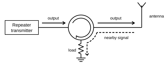
Key Information:
- Intermodulation between nearby repeaters can occur when their output signals mix in the final amplifier of one or both transmitters.
- A properly terminated circulator at the repeater transmitter’s output can reduce or eliminate intermodulation caused by a nearby transmitter.
The load absorbs the diverted energy. Without it, the third port reflects that energy onward to the transmitter, defeating the isolation.
Stop Noise Along Its Path #
Ferrite chokes on cables are a familiar cure for RF interference. They act on only one kind of current. The intended differential current goes out on one conductor and returns on another. Current can also flow the same way on every conductor at once. With no return path inside the cable, it returns outside, through stray capacitance to the surroundings, and the cable acts as an antenna. A shield doesn’t prevent this, because the same current can flow on the outside of the shield as well.
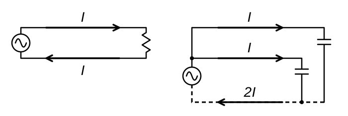
Key Information:
- Current flowing equally on all conductors of an unshielded multiconductor cable is common-mode current.
- Common-mode currents on the shield and conductors can cause shielded cables to radiate or receive interference.
The choke adds RF impedance to common-mode current while leaving the differential current largely alone. Put it where that impedance interrupts the noise path, ideally close to the source before a long cable radiates the noise.
Match the remedy to the conductors that carry the noise. In a vehicle, noise from the battery charging system travels along the charging leads. A line-driven AC motor sends its noise back along its power leads. A brute-force filter is a low-pass filter for the power line: series inductors and capacitors across the line pass the load current while blocking RF.
Key Information:
- Ferrite chokes on automobile battery charging-system leads can suppress conducted noise from that system.
- A brute-force AC-line filter in series with a line-driven AC motor’s power leads suppresses its RF interference.
Use a filter rated for the voltage and current; installing it in mains wiring is electrical work, not a job for loose components. After any remedy, repeat the original listening test to confirm that the change fixed the problem.




 Switch-mode power supplies