

Section 6.9: Receiving Antennas #
For transmitting, losing most of the accepted power is disappointing. For receiving on a noisy low band, a lossy antenna can still be excellent if it rejects more noise than wanted signal. Switch to it and the S-meter may fall while the words become easier to copy. For this job, signal-to-noise ratio matters more than a large meter reading.
Listen in Fewer Directions #
On 160 and 80 meters, atmospheric noise usually far exceeds the receiver’s own noise. Antenna loss weakens the wanted signal and that noise together, so their ratio stays the same. That holds until the loss grows large enough for the receiver’s own noise to matter. Directivity can improve the ratio by favoring the wanted station while rejecting noise from other directions.
A deep rear null helps against one noise source, but noise can come from all around. Receiving directivity factor, or RDF, rates how well an antenna rejects all of it.
Key Information:
- For 160- and 80-meter receiving antennas, atmospheric noise is generally so high that directivity is much more important than losses.
- Receiving directivity factor (RDF) is peak antenna gain compared to average gain over the hemisphere around and above the antenna.
That average includes every direction above the ground, not only the rear, so RDF tells you more than a front-to-back ratio does.
A Long Wire Near the Ground #
The Beverage, a long, low wire with a resistor at its far end, is the classic low-band receiving antenna. It works like the terminated long wire in Section 6.4. The wire points toward the wanted stations, with the receiver connection at the near end and the termination at the far end. A signal from the favored direction travels along the wire toward the receiver, and the voltages it induces add along the way. A signal from behind builds up toward the far end instead, where it meets the resistor rather than an open end that would reflect it back toward the receiver.
The resistor works best when it matches the wire’s own characteristic impedance, typically several hundred ohms. With the wrong value, waves reaching the far end partly reflect. As on any mismatched line in Section 6.3, the feed impedance then varies more as frequency changes.
Directivity grows with length. For scale, one wavelength at 1.8 MHz is about meters. A Beverage needs room to roam, often more than a suburban lot can offer, though it does not need a high tower.
Key Information:
- The function of a Beverage antenna’s termination resistor is to absorb signals from the reverse direction.
- Minimum variation in SWR over the desired frequency range indicates the correct value of terminating resistance for a Beverage antenna.
- To achieve good performance at the desired frequency, a Beverage antenna should be at least one wavelength long.
Stronger Loop Output #
Where a Beverage won’t fit, a small receiving loop offers a compact alternative. If its output is too low, a larger area intercepts more changing magnetic flux, while more turns add their induced voltages.
Key Information: The output voltage of a multiple-turn receiving loop antenna can be increased by increasing the number of turns and/or the area enclosed by the loop.
Sharper Nulls for Direction Finding #
For direction finding, or DF, a small loop’s deep null is often easier to locate precisely than its broad maximum. The loop responds mainly to the wave’s magnetic field. Stray capacitance to its surroundings, unequal on its two sides, adds some electric-field pickup. That unbalanced capacitive coupling makes the loop act partly like a small whip, which hears every direction and so fills the nulls. An electrostatic shield, a conducting tube around the loop, intercepts that electric field before it reaches the wire. The shield has a gap so it doesn’t form a closed turn, which would block the magnetic field as well.
Key Information: An electrostatic shield around a small-loop direction-finding antenna eliminates unbalanced capacitive coupling to the antenna’s surroundings, improving the depth of its nulls.
One Null Instead of Two #
Even a perfect null leaves a question: which end of the bearing points to the transmitter? Rotating the loop until the signal disappears identifies an axis, leaving the source ahead or behind. On a fox hunt, that ambiguity can send you to the wrong side of town.
Key Information: The challenge presented by a small wire-loop antenna for direction finding is that it has a bidirectional null pattern.
The loop’s two lobes have opposite phase: signals from opposite sides produce voltages of opposite polarity. A sense antenna, usually a short vertical, adds back the whip-like response the shield removed, this time on purpose, at a controlled phase and level. It reinforces one lobe and cancels the other, leaving a pattern shaped like that of the phased verticals in Section 6.6.
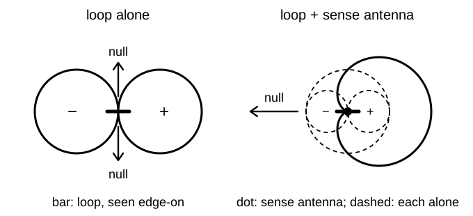
A pennant produces that pattern by itself. It is a single-turn loop shaped like a flag, with a resistor on the side opposite its feed point. It sums its own electric- and magnetic-field pickup, much as a loop and sense antenna do, with the resistor setting the balance.
Key Information:
- The function of a sense antenna is to modify the pattern of a DF antenna to provide a null in only one direction.
- A single-turn, terminated loop such as a pennant antenna creates a cardioid radiation pattern.
- A single null is the feature of a cardioid pattern that makes it useful for direction-finding antennas.



 Atmospheric noise is so high that directivity is much more important than losses