

Section 6.6: Arrays and Reflectors #
A Yagi favors one direction, and changing that direction means turning the antenna. Two fixed verticals can favor a direction too, then point another way at the flip of a switch in the shack; only their feed changes. In the pair, as in the Yagi, fields from separate elements meet at a distant point. Like ripples spreading from two pebbles dropped in a pond, they add in some directions and cancel in others. Spacing and the phase of each element’s current decide which directions are which.
Feed Phase and Travel Phase #
Here both verticals are driven elements. Phasing lines, lengths of feed line that delay the signal to one element, set the phase of each element’s current. At a distant point, the phase difference between the two fields combines that feed delay with the extra distance one field travels. The pattern follows from the total.
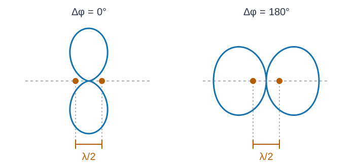
The array axis is the line joining the antennas. Consider two quarter-wave verticals spaced half a wavelength apart, with equal currents in phase. Broadside to the axis, the travel distances are equal, so their fields add. Along the axis, the extra half wavelength of travel adds 180 degrees, so their fields cancel.
Now feed the same elements 180 degrees apart. Broadside, their fields cancel. Along the axis, a direction sometimes called end-fire, the extra travel delay makes up for the feed-phase difference, so the fields arrive in step and add.
Key Information:
- The purpose of using multiple driven elements connected through phasing lines is to control the antenna’s radiation pattern.
- Two 1/4-wavelength vertical antennas spaced 1/2-wavelength apart and fed in phase create a figure-eight pattern broadside to the axis of the array.
- The same pair fed 180 degrees out of phase creates a figure-eight pattern oriented along the axis of the array.
Quarter-wave spacing and a 90-degree feed difference give another useful pattern. Along one direction, the travel delay makes up for the feed delay, so the fields arrive in step and add. In the opposite direction, the two phase differences total 180 degrees, so the fields cancel and produce a null. The favored direction points from the element whose feed leads toward the one that lags, so reversing which element leads reverses the pattern.
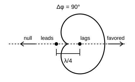
Key Information: Two 1/4-wavelength vertical antennas spaced 1/4-wavelength apart and fed 90 degrees out of phase create a cardioid radiation pattern.
The depth of the null is a useful check on construction: amplitude or phase errors fill it in.
Phase From Parasitic Elements #
A Yagi obtains useful phase differences without feeding every element. Only its driven element connects to the feed line. Fields from it induce currents in the parasitic elements, and those elements reradiate. The phase of each induced current depends on the element’s length and spacing. An element longer than resonant length is inductive, so its current lags the voltage induced in it. A shorter element is capacitive, like the short whip in the previous section, so its current leads. As with the phased verticals, that phase and the spacing together decide on which side the fields add. That is why designers make a reflector longer than resonant length and a director shorter.
A two-element Yagi can use either one. A reflector usually sits around 0.15 to 0.2 wavelength from the driven element. A director does as well only at closer spacing, about 0.1 wavelength, where the feed resistance falls low enough to make matching harder.
Key Information:
- A Yagi’s driven element is approximately 1/2 wavelength long.
- The purpose of making a Yagi’s parasitic elements either longer or shorter than resonance is control of phase shift.
- Most two-element Yagis with normal spacing have a reflector instead of a director for higher gain.
Rotating the Polarization #
A 90-degree phase difference can also set polarization. Circular polarization, often used for satellite work, comes from two perpendicular linear fields of equal strength, a quarter cycle apart, as Section 6.1 showed. Two Yagis can supply those fields when they share one boom with their elements at right angles. Their driven elements must sit at the same point along the boom, because an offset would add its own travel phase.
Key Information: Two linearly polarized Yagi antennas can produce circular polarization when arranged on the same axis and perpendicular to each other, with the driven elements at the same point on the boom and fed 90 degrees out of phase.
Dish Gain and Frequency #
A parabolic dish, the shape familiar from satellite TV, reflects energy from a feed at its focus into a narrow beam. Its gain is proportional to its area measured in square wavelengths, so the same dish has more gain on a higher band. Doubling frequency halves wavelength. The dish then spans twice as many wavelengths across, so its area in square wavelengths, and its gain, grow by a factor of four.
Key Information: Doubling the operating frequency increases the gain of an ideal parabolic reflector antenna by 6 dB.
A real dish delivers that full increase only if its surface accuracy and feed still perform well at the higher frequency. Its narrower beam also demands more careful pointing.




 To control the antenna’s radiation pattern