

Section 6.3: Feed Line Behavior #
On a mismatched feed line, forward and reflected waves combine into a standing wave, with voltage peaks and dips at fixed points along the line. SWR sums up that pattern in one number, the ratio of the highest voltage to the lowest. Voltage and current vary from point to point, so the impedance does too, and a line cut to a chosen length can become a matching component, built from nothing but coax.
Wavelength Inside the Line #
A matching section needs a particular electrical length: the fraction of a wavelength it spans, measured inside the line. Its physical length depends on how fast the wave travels there, and the line’s dielectric, the insulating material between its conductors, slows the wave. A velocity factor, VF, describes that speed:
A slower wave has a shorter wavelength. If VF is 0.66, a wave travels only 66% as far during one cycle as it would in free space. To find the physical length for a chosen fraction of a wavelength, multiply the free-space length by VF.
A free-space wavelength in meters is about 300 divided by the frequency in megahertz. For an air-insulated parallel line at 14.10 MHz, VF is approximately 1, so a half wavelength is
The same electrical length in VF 0.66 coax is about meters. Cut the coax to 10.6 m, and you’d miss by more than 3 meters.
Key Information:
- The velocity factor of a transmission line is the velocity of a wave in the transmission line divided by the velocity of light in a vacuum.
- The insulating dielectric material has the biggest effect on the velocity factor of a transmission line.
- The electrical length of a coaxial cable is longer than its physical length because electromagnetic waves move more slowly in a coaxial cable than in air.
- An air-insulated, parallel conductor transmission line that is electrically 1/2 wavelength long at 14.10 MHz is approximately 10.6 meters long.
Loss and Construction #
The plastic that slows the wave in coax also absorbs some of its energy, and conductor resistance turns more into heat. Parallel line held apart mostly by air has little plastic to absorb energy.
Foam dielectric replaces much of the solid plastic with gas, leaving less material to slow the wave or absorb it. Gas also breaks down at a lower voltage than solid plastic. Check the maker’s rating for a particular cable.
A line’s build also sets its characteristic impedance. Conductor size, spacing, and the dielectric between them all count. Copper traces on a circuit board work the same way. At microwave frequencies, even a trace a few centimeters long spans a large part of a wavelength. It acts like a feed line, so any change in its impedance causes reflections.
Key Information:
- Parallel conductor transmission line has lower loss than coaxial cable with a plastic dielectric.
- Assuming all other parameters are the same, foam dielectric coaxial cable has lower safe maximum operating voltage, lower loss per unit of length, and higher velocity factor than solid dielectric coaxial cable.
- Microstrip consists of precision printed circuit conductors above a ground plane that provide constant impedance interconnects at microwave frequencies.
Reflections and Standing Waves #
Predicting the impedance at each point takes more than SWR. It takes the size and the phase of the reflected wave. A load equal to the line’s characteristic impedance, , produces no reflection.
The reflection coefficient, (capital gamma), gives the reflected voltage wave relative to the incident voltage wave, including phase. For a load impedance ,
Key Information: Reflection coefficient is the parameter that describes the interaction of a load and transmission line.
For a 100-ohm resistive load on 50-ohm line, . The reflected power fraction is , about 11%. SWR follows from the size of :
That matches the shortcut for a resistive load: .
Impedance Along a Line #
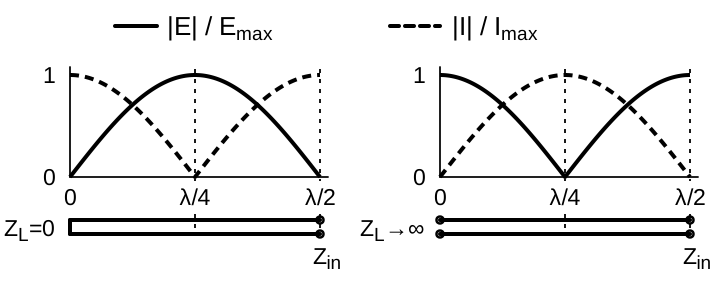
To use a line as a matching component, follow how the reflected wave’s phase changes along it. That changes the local voltage-to-current ratio, and therefore the impedance seen at each point. Where voltage is high and current approaches zero, their ratio gives very high impedance. Where voltage approaches zero and current is high, impedance is very low. An ideal half-wave line repeats its terminating impedance; a quarter-wave line inverts it.
Key Information:
- A 1/2-wavelength transmission line shorted at the far end presents very low impedance to an RF generator.
- A 1/4-wavelength transmission line shorted at the far end presents very high impedance to an RF generator.
- A 1/4-wavelength transmission line open at the far end presents very low impedance to an RF generator.
Matching may also call for a particular reactance rather than an open or a short. A short section of line with a shorted or open end can supply one; used this way, it is called a stub. When a stub is shorter than a quarter wave, a shorted end keeps current high and voltage low over most of its length, so the stub stores mostly magnetic energy. An open end does the reverse, so an open stub stores mostly electric energy.
For electrical length in degrees, a lossless shorted stub has ; an open stub has . At one-eighth wavelength, and .
Key Information:
- A 1/8-wavelength transmission line shorted at the far end presents an inductive reactance to an RF generator.
- A 1/8-wavelength transmission line open at the far end presents a capacitive reactance to an RF generator.
An eighth-wave stub of 50-ohm line therefore supplies about when shorted, or when open.



 The velocity of a wave in the transmission line divided by the velocity of light in a vacuum