

Section 3.5: Oscillators and Phase Locking #
An amplifier that oscillates by accident needs a suppressor. One that oscillates on purpose is an oscillator: an amplifier and a filter in a feedback loop, with the filter picking the frequency. How steady that frequency stays depends mostly on the filter’s resonator. Nearby circuits, vibration, and heat can all pull the frequency.
Quartz Resonance #
Many oscillators use a quartz crystal as their resonator. Quartz is piezoelectric, a property that links its mechanical vibration to the electrical signal.
Key Information:
- Piezoelectricity is a characteristic of materials that generate a voltage when stressed and that flex when a voltage is applied.
- Mechanical deformation of material due to the application of a voltage is an aspect of the piezoelectric effect.
A cut piece of quartz vibrates best at frequencies set mainly by its size and the angle of the cut. Electrodes on its surfaces connect the circuit to those vibrations. The quartz loses very little energy per cycle, so its resonance has a very high Q, far above an ordinary LC circuit’s.
To see how nearby circuits affect that resonance, we model the crystal with electrical parts. An inductance stands for the quartz’s moving mass, a capacitance for its springiness, and a resistance for its loss. The electrodes, with quartz between them, also form a small capacitor of their own.
Key Information: The equivalent circuit of a quartz crystal is a series RLC in parallel with a shunt C representing electrode and stray capacitance.
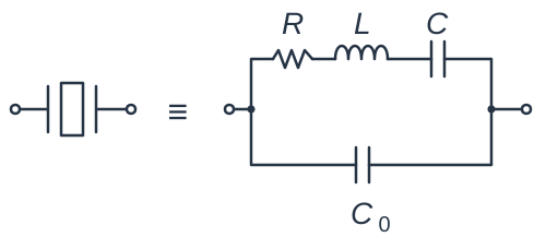
The RLC branch has low impedance at its series resonance. Above that frequency, the branch acts inductive, so its current opposes the shunt C’s current. A little higher, the two currents cancel, giving a high-impedance parallel resonance. Between the two resonances, the crystal acts like an inductor. Capacitance outside the crystal sets where in that narrow range the oscillator runs.
Returning the Signal in Phase #
The resonator picks the frequency; the amplifier and feedback path keep the oscillation going. The feedback must be positive: the returning signal arrives in step with the circulating one, for a total phase shift around the loop of zero or a whole 360°. The amplifier’s gain must also start out larger than the losses around the loop. As the signal grows, the amplifier’s own limits hold it at a steady level.
The classic oscillator circuits, each named for its inventor, differ in how they return part of the output. A Hartley oscillator taps its coil, making an inductive voltage divider. Splitting the resonant circuit’s capacitance into two capacitors in series makes a capacitive divider instead, tapped where they meet. Another approach sends the feedback through a quartz crystal, whose sharp resonance then sets the frequency.
Key Information:
- Colpitts, Hartley, and Pierce are three common oscillator circuits.
- Positive feedback is supplied in a Colpitts oscillator through a capacitive divider.
- Positive feedback is supplied in a Pierce oscillator through a quartz crystal.
A typical Pierce oscillator resembles a Colpitts, with the crystal in place of the coil. Running between its two resonances, the crystal acts as the inductor, and a capacitor runs from each end of it to ground. Those capacitors help set the frequency. A crystal made for this circuit is rated for a certain load capacitance, the capacitance the circuit puts in parallel with it; crystals for series-resonant circuits are rated without one. In the Pierce circuit, the crystal sees the two capacitors in series, through ground. Two 20 pF capacitors give 10 pF, plus a little stray capacitance from the board.
Key Information: Providing the crystal with a specified parallel capacitance ensures that a crystal oscillator operates on the frequency specified by the crystal manufacturer.
Keeping Frequency Steady #
Vibration is another threat. A jolt can flex a part, shift a wire, or change a stray capacitance just enough to move the frequency. The oscillator then acts a bit like a microphone, turning sound and bumps into changes of frequency. Tap the cabinet, and the signal you’re listening to may wobble in pitch. Those bumps reach the circuit through whatever holds it, usually the case.
Heat is a third. It changes component values and the crystal itself. A capacitor whose value drifts with temperature drags the frequency along. NP0 capacitors, also marked C0G, use a ceramic whose value barely changes with temperature. They hold the oscillator’s load capacitance steady.
Key Information:
- A microphonic is a change in oscillator frequency caused by mechanical vibration.
- An oscillator’s microphonic responses can be reduced by mechanically isolating the oscillator circuitry from its enclosure.
- NP0 capacitors can be used to reduce thermal drift in crystal oscillators.
Small drifts matter more as frequency rises. A drift of one part per million moves a 10 MHz oscillator 10 Hz but a 10 GHz oscillator 10 kHz. When a crystal alone isn’t stable enough, a steadier reference can correct the oscillator. GPS satellites broadcast timing taken from atomic clocks, and a rubidium oscillator holds its frequency to an atomic transition. A microwave oscillator can also use a dielectric resonator, a low-loss ceramic piece that stores microwave energy.
Key Information: Microwave transmission and reception need highly accurate and stable oscillators. Techniques for providing them include a GPS signal reference, a rubidium stabilized reference oscillator, and a temperature-controlled high-Q dielectric resonator.
Locking to a Reference #
A GPS or rubidium reference usually doesn’t produce a radio’s working frequency. It corrects an oscillator that does, so that oscillator must be adjustable. In a voltage-controlled oscillator, or VCO, changing the control voltage changes the frequency. A circuit that compares phase supplies the correction.
In a phase-locked loop, or PLL, a phase detector compares the reference signal with a signal taken from the VCO’s output. A low-pass filter smooths the detector’s correction signal. That voltage adjusts the VCO, reducing the phase error. Like any servo, the loop keeps correcting the difference between what is wanted and what is happening.
Key Information: A phase-locked loop is an electronic servo loop consisting of a phase detector, a low-pass filter, a voltage-controlled oscillator, and a stable reference oscillator.
A frequency divider in the feedback path lets the loop run the VCO at a multiple of the reference frequency. A divide-by-100 stage puts out one cycle for every 100 it receives. Compare its output with a 1 MHz reference, and the loop brings the divided signal to 1 MHz. The VCO then runs at 100 MHz.
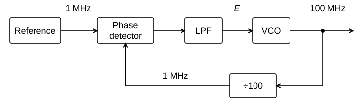
Follow the return path: the detector compares two 1 MHz signals, though the useful output is 100 MHz. If the VCO drifts, the comparison changes and the loop corrects it. Divide by 101 instead, and the VCO settles at 101 MHz, with no extra crystal needed.
A loop can also track a received FM signal fed to its phase detector in place of the reference. As the carrier frequency swings, the loop moves its VCO to stay with it. The VCO’s frequency follows its control voltage, so that voltage becomes a copy of the original audio.
Key Information: Frequency synthesis and FM demodulation are functions that can be performed by a phase-locked loop.



 A characteristic of materials that generate a voltage when stressed and that flex when a voltage is applied