

Section 2.5: Real Components at RF #
You buy an inductor for its inductance, but you get some capacitance and resistance with it at no extra charge. A capacitor brings unwanted inductance too. This chapter’s calculations have treated parts as ideal. At RF, those extras can grow large enough to change the answer, so a correct value on the label does not guarantee the right behavior.
Current Crowds Toward the Surface #
A wire’s DC resistance can underestimate the loss it causes at RF. DC uses the whole cross section evenly, but an alternating current’s own changing magnetic field pushes it toward the conductor’s surface, more strongly as frequency rises. This is skin effect. At 14 MHz, most of the current in a copper wire flows within about 0.02 mm of the surface, a layer thinner than a sheet of paper.
Capacitors have metal in their current path too. In a film capacitor, a thin plastic film separates the electrodes. A low-loss film such as polypropylene wastes little energy itself, so most of the loss comes from resistance in the metal: the electrodes, end connections, and leads.
Key Information:
- Conductor skin effect increases resistance as frequency increases because RF current flows closer to the surface.
- Skin effect is the primary cause of loss in film capacitors at RF.
A Connection Is a Component #
Long leads kept DIP packages out of UHF circuits in the previous chapter. Even a straight lead has inductance, and since , a lead that contributes little reactance at audio frequencies can become troublesome at VHF.
Travel time is the other cost. At microwave frequencies, a connection can occupy a noticeable fraction of a wavelength. The signal takes time to travel along it, so its phase at one end differs from its phase at the other. Physical layout becomes part of the circuit.
Key Information:
- Short component leads at VHF and above minimize inductive reactance.
- Short connections at microwave frequencies reduce phase shift along the connection.
A circuit that works with short connections may fail when you spread the same parts across a breadboard, even though the schematic hasn’t changed. At RF, the layout belongs in the troubleshooting process.
Unwanted Resonance #
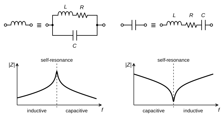
Neighboring turns of a coil are conductors separated by insulation and air, so they form small capacitors. Together with the coil’s own inductance, they make a resonant circuit inside the part. Above that self-resonant frequency, the coil acts more like a capacitor.
Capacitors have the reverse problem. Their leads and plates add a little series inductance. Above the resulting self-resonance, a capacitor acts more like an inductor. Each part has the reactance you bought it for, its nominal reactance. It also has an unwanted parasitic reactance of the opposite kind. The figure below models both parts and sketches how each one’s impedance changes with frequency.
Key Information:
- Inter-turn capacitance creates an inductor’s self-resonance.
- A component’s nominal reactance and parasitic reactance combine to create self-resonance.
Self-resonance limits which parts suit a job. An RF bypass capacitor provides a path for unwanted RF current around part of a circuit, often to ground. An aluminum electrolytic capacitor gets its large capacitance from long strips of foil rolled up inside a sizable case, and that construction brings series inductance with it. A bigger one can even be worse: its larger case usually adds inductance, which lowers its self-resonance and raises its impedance at VHF.
Key Information: Parasitic inductance makes electrolytic capacitors unsuitable for use at RF.
An electrolytic can still smooth low-frequency supply ripple. A smaller capacitor designed for RF can handle the higher-frequency current nearby.
Two Kinds of Length #
A loading coil or capacitance hat can make a short mobile antenna act longer than it is. It adds electrical length, which describes how long a conductor acts at a given frequency, measured in wavelengths or degrees of phase. A conductor’s own thickness has a similar, smaller effect. A thicker conductor has more capacitance, especially near its ends, so it resonates at a lower frequency than a thin one of the same physical length, just as a longer conductor would.
Key Information: As a conductor’s diameter increases, its electrical length increases.
To resonate at the same frequency, a thicker antenna element needs a slightly shorter physical length. We will use that distinction again when discussing antennas and feed lines in Chapter 6.



 Resistance increases as frequency increases because RF current flows closer to the surface