

Section 2.4: Resonance and Q #
Inductive reactance rises with frequency while capacitive reactance falls, so an inductor and a capacitor have one frequency where their reactances are equal. That is their resonant frequency, the one a tuned circuit picks out. In series, the pair draws its greatest current from the source there; in parallel, it draws its least. Either way, the voltages or currents inside the circuit can be much larger than the source’s own.
Two Resonant Arrangements #
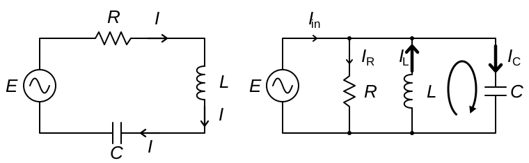
At resonance, energy keeps moving between the electric and magnetic fields, but their opposite phase effects cancel at the input. In a series RLC circuit, the net reactance is zero, so the phase angle is . With only resistance left to limit it, the current through all the components reaches its maximum for a fixed applied voltage.
That large current flows through the inductor and capacitor too. Suppose a 10 V source drives 1 A through 10 Ω of resistance. The resistor drops the full 10 V. If the inductor and capacitor each have 100 Ω of reactance, that same current produces 100 V across each one.
Energy passing between the inductor and capacitor sustains those larger voltages. Their voltages are opposite in phase, so they cancel around the complete circuit. The source supplies only the energy lost in the resistance. This is why a small transmitting loop’s tuning capacitor can need a rating of several thousand volts, even at modest power.
Key Information:
- At series resonance, voltage and current are in phase, and the impedance magnitude is approximately equal to circuit resistance.
- Resonance can make the voltage across individual reactances in a series RLC circuit higher than the voltage applied to the entire circuit.
A parallel resonant circuit presents the opposite pattern at its input. Both branches share the same voltage. Capacitor current leads that voltage by 90°, while inductor current lags it by 90°, so their currents are 180° apart.
Away from resonance, one branch draws more current than the other. Only the smaller current can circulate between them, and the source supplies the difference. At resonance the two are equal, so they cancel completely at the input and all of the branch current circulates between L and C. With little loss, the circulating current can be many times the input current.
The resistance in this parallel model sits across the LC pair. At resonance, the source supplies only the current through that resistance. This resistance is usually large, unlike the small wire resistance in series with a coil. That is why a parallel tuned circuit such as an antenna trap presents a high impedance at resonance. It is high in ohms, but no higher than the parallel resistance itself.
Key Information: At parallel resonance:
- The impedance magnitude is approximately equal to the circuit’s parallel resistance.
- Circulating current within the LC components is at a maximum.
- Current at the circuit’s input is at a minimum.
Finding the Resonant Frequency #
The resonance formula comes from setting . With inductance in microhenries and capacitance in picofarads, a convenient form gives resonant frequency in megahertz:
The number 159.2 includes and the unit conversions, so the values marked on the parts go straight in.
Take an RLC circuit with 22 Ω of resistance, 50 µH, and 40 pF. The resistance affects loss and the sharpness of resonance, but it does not enter this ideal LC frequency calculation. Work through three operations:
- Multiply: .
- Take the square root: .
- Divide: .
Change the parts to 33 Ω, 50 µH, and 10 pF. The resistance again drops out. The product is 500 and its square root is about 22.36. Dividing 159.2 by 22.36 gives 7.12 MHz. Reducing the capacitance to one quarter has doubled the frequency.
Key Information:
- With , , and , resonance is at 3.56 MHz.
- With , , and , resonance is at 7.12 MHz.
You may also see the formula written as . That version uses henries and farads and gives hertz.
How Sharply It Resonates #
Two circuits can tune to the same frequency yet respond differently on either side of it. The quality factor, , measures that sharpness by comparing energy stored with energy lost. A high-Q circuit loses a smaller fraction of its stored energy each cycle. Like a well-made bell that keeps ringing after one strike, it hangs on to its energy.
Where the resistance sits decides how to calculate Q. Series resistance carries the full circuit current, so less of it wastes less power; a series RLC model uses . Parallel resistance sits across the full voltage, so more of it draws less current and wastes less power; a parallel model turns the ratio over, . At resonance the two reactances are equal, so either one gives the same Q. In our earlier series example, , and each reactance had ten times the source voltage.
Key Information:
- For a parallel RLC resonant circuit, calculate Q by dividing resistance by the reactance of either the inductance or capacitance.
- Increasing Q in a series resonant circuit increases internal voltages.
To put a frequency range to that sharpness, measure the half-power bandwidth between the response points on either side of resonance. At each point, power is half its resonant value, 3 dB below the peak. Bandwidth spans the whole interval, not the distance from the peak to one side.
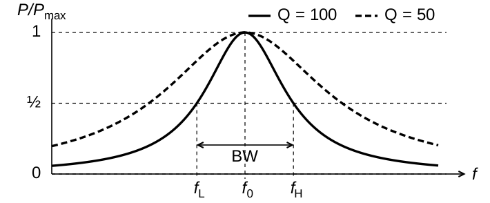
In the tuned-circuit model used here, bandwidth is the resonant frequency divided by Q:
Try a circuit tuned to 7.1 MHz with a Q of 150. First write the frequency as 7100 kHz. Dividing gives a bandwidth of 47.3 kHz. Starting in kilohertz makes the answer come out in kilohertz.
At 3.7 MHz with a Q of 118, use 3700 kHz: .
The same formula runs backward: . Use the same frequency units for both numbers. A response centered on 7100 kHz with a bandwidth of 47.3 kHz gives for Q.
A sharper response is useful when selecting one frequency, but it also narrows the range a circuit can cover without retuning. An impedance-matching network, such as the one in an antenna tuner, is a tuned circuit too, and its Q sets how far you can change frequency before you lose the match.
Key Information:
- A circuit resonant at 7.1 MHz with Q of 150 has a half-power bandwidth of 47.3 kHz.
- A circuit resonant at 3.7 MHz with Q of 118 has a half-power bandwidth of 31.4 kHz.
- The bandwidth of a series-tuned circuit’s frequency response can be used to determine its Q.
- Increasing the Q of an impedance-matching circuit decreases its matching bandwidth.
Once the circuit is connected, its source and load draw energy from it too, lowering its Q and broadening its response.



 The voltage and current are in phase